Engineering 101: Three Ways Heat Can Transfer
- Read more about Engineering 101: Three Ways Heat Can Transfer
- Log in or register to post comments
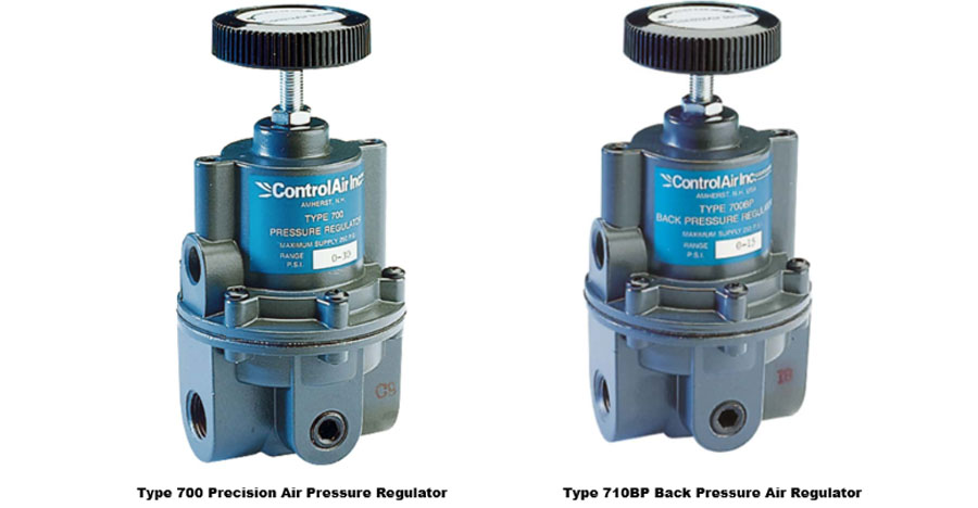
Back Pressure Regulator vs. Pressure Regulator: What’s the Difference and When to Use Each
ControlAir
In many industrial and pneumatic systems, pressure control is essential. But not all pressure regulators are created equal. Two of the most commonly used devices—pressure regulators and back pressure regulators—perform very different roles. Choosing the right one depends on where you need to control pressure in your system.
In this post, we’ll explain the key differences between a pressure regulator and a back pressure regulator, highlight typical applications, and help you determine which is best for your system.
What Is a Pressure Regulator?
A pressure regulator (also known as a pressure reducing regulator) is used to control downstream pressure. It is installed upstream of the equipment that requires consistent, reduced pressure. Its main function is to take high inlet pressure and reduce it to a controlled, lower outlet pressure.
As the downstream pressure drops, the pressure regulator opens to allow more flow. As pressure builds back up, it closes to maintain the desired setpoint.

Common Pressure Regulator Applications:
- Supplying compressed air to pneumatic tools
- Delivering controlled pressure to process instruments
- Maintaining stable gas pressure in distribution systems
Bottom line: A pressure regulator ensures that what comes after it in the system receives a steady, manageable pressure.
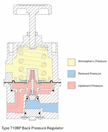
What Is a Back Pressure Regulator?
A back-pressure regulator works in the opposite direction. It controls upstream pressure, ensuring that pressure on the inlet side of the valve does not exceed a set level. When the upstream pressure gets too high, the back pressure regulator opens to bleed off excess pressure.
This type of regulator is typically installed downstream of the area where pressure needs to be maintained. Think of it as an adjustable relief valve that keeps upstream systems from becoming over-pressurized.
Common Back Pressure Regulator Applications:
- Controlling pressure in closed-loop systems
- Maintaining pressure in chemical reactors or tanks
- Regulating pump discharge pressure
- Managing backflow in return lines
- Flow controllers
Bottom line: A back-pressure regulator protects the system by holding pressure in, then releasing it only when it rises too high.
Which Regulator Do You Need?
Choosing between a pressure regulator and a back-pressure regulator depends entirely on your system’s requirements:
- If your goal is to deliver a consistent pressure to a downstream device or process, use a pressure regulator.
- If you need to maintain a minimum pressure level in a vessel, loop, or upstream line, a back-pressure regulator is the right choice.
Need Help Selecting the Right Pressure Regulator?
Whether you’re trying to maintain steady output pressure or control upstream pressure build-up, ControlAir can help. We offer a full range of pressure regulators and back-pressure regulators designed for high performance in demanding industrial environments.
Talk to one of our experts today at (855) 737-4714, or fill out our online form to learn more.
Actuator vs. Stage vs. Positioner – What’s the Difference in Linear Motion Systems?
Corey Foster || Valin Corporation
Understanding Linear Motor Terminology for Better Motion System Selection
In industrial automation and motion-control systems we often use terms interchangeably, but words have meaning — and often carry very different technical implications.
- Linear motor actuators
- Linear motor stages
- Linear motor positioners
- Linear servo motor versions of all of the above
- Linear stepper motor versions, too
But, each of these linear motion terms has a nuanced meaning and technical implication when designing machine automation solutions. If you've ever found yourself asking "What exactly is a linear servo motor positioner versus a linear servo motor actuator versus a linear servo motor stage?" you're not alone. Let’s break this down clearly and simply.
What Is an Industrial Automation Actuator?
The word “actuator” is the most generic and widely used of the terms.
Definition: An actuator is any mechanism that causes motion.
Actuators can be:
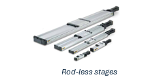
In the electric linear actuator world (whether servo linear actuator or stepper linear actuator), you’ll find rod-style, rodless, rack & pinion, direct-drive versions — all of which are key in industrial automation linear motion applications.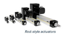 There are many form factors…
- Rod-style actuators
- Rodless actuators
- Rack & pinion driven
 …and transmissions…
- Ballscrew
- Belt & pulley
- Rack & pinion
- Direct drive
In short, “actuator” is your catch-all term. It could be low-end or high-end, simple or complex.
What is an Industrial Automation Stage?
A stage is a specific type of actuator with a particular structure and purpose.
Definition: A stage is a motion platform where the load sits on top, and the platform moves back and forth on a base.
Technically, a stage includes:
- A moving carriage or platform
- A base or frame
- A guide mechanism (bearings, rails)
- And usually, a motor and transmission causing motion
Stages often incorporate more precision components and tighter tolerances than generic actuators.
A linear stage or motorized linear stage is a specific type of actuator with guide rails, load-bearing carriage and base — often used in robotics, precision dispensing, semiconductor manufacturing and other motion-control systems requiring repeatability.
What is an Industrial Automation Positioner?
Now here’s where we bundle the full system together.
Definition: A positioner includes the mechanical stage/actuator, plus the control electronics, feedback, and even sometimes networking or communication protocols.
In other words, it’s a complete motion subsystem — not just the mechanics.
A linear positioner system combines the linear stage mechanics with control electronics, feedback encoder or resolver, networking and motion controller — in other words a full motion-positioning subsystem in factory automation or machine automation.
While a simple actuator might move with just a power source, a positioner is designed to move to an exact position, often based on external commands or automation systems. It includes:
- Motion controller
- Feedback device (like an encoder)
- Software or interface
- Safety and home limit sensors
This is where the difference in application complexity becomes important:
- Actuator = motion
- Stage = motion + structure
- Positioner = motion + structure + control
Definitions at a Glance
| Term | Description | Includes | Common Use |
|---|---|---|---|
| Actuator | Causes motion | May or may not include motor | Generic, all-purpose |
| Stage | A platform-style actuator with a carriage | Actuator + load-bearing structure | Precision setups |
| Positioner | Full positioning system with control | Stage + controls + feedback | Automated systems needing precision |
Choosing Between an Actuator, Stage, and Positioner
The choice depends on your application requirements. If you simply need linear motion, an actuator might be sufficient. If you need guidance and precision, you move up to a stage. And if you need integrated feedback, closed-loop control, and coordinated automation, then a positioner is the right fit.
When specifying a linear motion system, consider:
- Required stroke length — short or long stroke
- Desired precision and repeatability
- Load capacity and duty cycle
- Motor type (rotary, stepper, or linear motor)
- Control architecture and feedback needs
Matching the right motion component to the right automation task is where application engineering expertise makes all the difference.
Understanding the other words: “Linear,” “Servo,” and “Motor”
Here are a few other foundational terms that often get bundled with actuators, stages and positioners:
Linear: This just means straight-line motion (as opposed to rotary). So everything we’re discussing here involves motion along a linear path but there are rotary equivalents.
Motor: The motor is the source of movement as opposed to it being pneumatic or hydraulic. There are fluid power motors, but typically a motor is assumed to be electric which are typically either servo or stepper technology.
Servo vs. Stepper
- Servo motors are controlled by closed-loop systems, which means they constantly adjust to maintain precise position, speed, and torque. This is ideal for dynamic, high-speed, or high-accuracy applications.
- Stepper motors are usually controlled by open-loop controllers. They move in steps and are simpler, but typically lower in performance and accuracy. However, there are closed-loop systems that use stepper motors instead of servos.
So, when we say:
- Linear Servo Motor Actuator – we’re talking about a straight-line motion device powered by a servo motor.
- Linear Stepper Motor Stage – we mean a stage-style mechanism powered by a stepper motor.
Now, let’s tackle the most confusing part: the difference between actuator, stage, and positioner.
Where Do Servo and Stepper Fit In?
Linear Servo Motor Actuators / Stages / Positioners
- Used when high accuracy, speed, and repeatability are required
- Feature feedback and closed-loop control
- Ideal for industrial automation, robotics, precision dispensing, lab automation, semiconductor, etc.
Linear Stepper Motor Actuators / Stages / Positioners
- More cost-effective
- Suitable for simpler or open-loop applications
- Ideal for basic positioning tasks or low-speed automation
- Not very common
Benefits and Why This Matters
Using the right keyword — whether you’re talking about a linear actuator, linear stage, or linear positioner — helps engineers, machine builders and purchasing teams clearly understand what kind of linear motion system you’re specifying and ensures you match the right solution in your automation application engineering.
If you're building or automating machinery and you’re unsure whether you need a linear actuator, stage, or positioner, or if you’re trying to decide between servo and stepper, Valin’s motion control engineers can help.
How to Select Linear Servo Motor Stages, Actuators and Positioners?
Aluminum Extrusion Cut Center
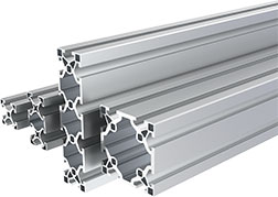 When it comes to building reliable, modular automation solutions, precision matters. That’s why Valin has invested in a dedicated Aluminum Extrusion Cut Center, making it simple for our customers to go from design concept to finished assembly.
Through our partnership with Robotunits, Valin offers a streamlined, end-to-end service for aluminum extrusion projects.
Custom Designs
Our engineering team can design to your specifications or provide expert frame design guidance that saves time, reduces complexity, and drives project success.
Precision Cut Center
Our in-house cut center maintains the Southwest’s largest inventory of Robotunits aluminum extrusion—covering all shapes, sizes, and accessories—ready for quick turnaround. From the final design we can cut extrusions to length and perform any required machining operations, ensuring accuracy and repeatability of each part.
Kitting Services
For Customers who prefer to do final assembly at their site, we organize and package all cut and machined extrusions and accessories, so your team receives everything ready to assemble—complete with detailed assembly drawings, bubble callouts, and matching tags for fast, error-free builds. Delivered exactly how you need them—minimizing handling and maximizing productivity.
Final Product Builds
Backed by our streamlined process from design to BOM to cut instructions to assembly, we deliver fully assembled, application ready solutions. Final builds often include incorporating other components of our extensive motion control and automation offering, along with key safety products.
Why Partner with Valin + Robotunits?
By combining Valin’s local cut center and inventory with Robotunits’ advanced modular automation technology, we offer customers a faster, more flexible path to production. Whether you need guarding, machine bases, frames, conveyors, or custom structures, our team ensures you get the right solution—delivered on time and built to last.
Extrusion & Fastening Technology
- Extrusion Technology 40mm Series
- Extrusion Technology 50mm Series
- Fastening Technology 40mm Series
- Fastening Technology 50mm Series
- General Modular Accessories
Features and Benefits Extrusion & Fastening Technology
- Faster assembly due to ease of connections
- Ease of adjustment (micro adjustable)
- One T-slot size/commons connector equals less components
Safety Fence Systems
Conveyor Technology
- Belt Conveyors
- Modular Belt Conveyors
- Timing Belt Conveyors
- Power Roller Conveyor Systems
- Roller Conveyors without Drive
- Lift Station
- Side Guide Systems
- Conveyor Technology Accessories
MBS PickStar
Tote Systems
Linear Motions Systems
Multifunctional Accessories
- Conveyor Technology Accessories
- Linear Motion Systems Accessories
- Safety Fence Accessories
- General Modular Accessories
Tell us what you need by filling out the form below. Whether it’s individual extrusion profiles or a complete custom design, Valin has the expertise and resources to deliver.
If you have any questions or are just looking for some help, we're happy to discuss your application with you. Reach out to us at (855) 737-4716.
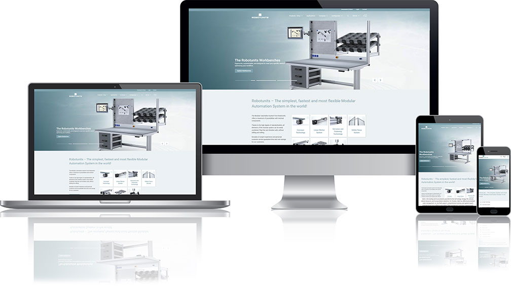
Robotunits Configurator
The Robotunits Configurator brings modular industrial automation design directly into your hands, empowering your engineering team with a guided, intuitive tool to build and visualize Robotunits systems. This interactive web tool allows engineers, integrators, and customers to select and combine modular components from the Robotunits product family—such as profiles, connectors, linear axes, conveyor modules, safety fences, and pick & place systems—and instantly visualize the assembled system in 3D or a realistic representation. Users can validate compatibility, clearances, mounting, and key parameters, while also generating a parts list, pricing estimate, and bill of materials (BOM). Technical drawings, CAD files, and order-ready documents can be easily exported, all without the need for CAD software or any special prior knowledge. The Configurator transforms what would otherwise be a manual, error-prone design and quoting process into a guided, efficient, and fully digital experience.
How The Robotunits Configurator Works
Select Modules & Layout: Start with base frame elements, profiles, brackets, extrusions, safety panels, etc. Arrange them in 3D space or guided layout mode.
Configure Motion, Conveyors & Accessories: Add linear axes, conveyor segments, lifting units, pick & place modules, etc. Tune parameters like stroke, load, speed.
Validate & Review: The tool checks constraints, collisions, and dependencies. You see visual cues or warnings for problematic areas.
Export & Order: Download CAD files, 2D drawings, complete parts list + pricing. Submit or forward directly for ordering or quoting.
Start Configuring Now
Just fill out the form below to access the Robotunits Configurator.
If you have any questions or are just looking for some help, we're happy to discuss your application with you. Reach out to us at (855) 737-4716 or fill out our online form.