Integrating Robots into Motion Control Systems
Tom Trinh || Valin Corporation

One of the most challenging elements to motion control is the integration of robots. However, the benefits that can be achieved through this type of integration cannot be understated. They will inevitably enhance the quality of the system and boost productivity. Thus, the exercise is well worth the investment. However, it can be a very daunting task if you aren’t as familiar with your options as you’d like to be.
In fact, there are four questions that you must address before walking through the decision tree of what robots will best fit your application:
- What level of speed do you need?
- How precise does the motion need to be?
- How adaptable does the robot need to be?
- How much is in your budget?
Once you have a solid foundation to work from by understanding the answers to these questions, you’re ready to work with an experienced professional to make the important decisions about which robots to integrate.
Cartesian robots are the simplest type to integrate. They are very flexible models, utilizing various technologies like ball screws and linear motors. This allows for configurations with more than two axes. These robots do tend to be a bit on the slower side, but the integration is very straightforward, making it the easiest to integrate. Cartesian robots are not very versatile, but they are also one of the more affordable options.
Selective Compliance Articulated Robot Arm (SCARA) models are very attractive to operators. They are very easy to integrate, have a very high speed and degree of precision and boast a moderate versatility. The price also is very middle-of-the-road, although a bit more expensive than the Cartesian variety.
Articulated robots can achieve high precision and is the most flexible of the models discussed here. It’s highly versatile but also requires a high level of programming expertise. And comes at a higher cost.
Collaborative robots or “cobots” are designed to collaborate with humans, so they allow for minimal integration. They typically operate at a lower speed and lower precision, but they rank high in terms of versatility. This is reflected in their higher price tag. If an activity may require on-the-fly adjustments by the operator, cobots may be the ideal choice.
The last element for consideration is maintenance. Operators are always trying to minimize downtime, so understanding the preventative maintenance requirements on these robots is critical. This requires a proactive effort to gather data for monitoring purposes.
I did a much deeper dive on the pros and cons of the different robot types for integrating into a motion control system last year in Control Design Magazine. For a little more in-depth discussion, be sure to check it out.
Talk to one of our experts today at (855) 737-4716 or fill out our online form to learn more.
Vision Integration Transforms Collaborative Robotics
- Read more about Vision Integration Transforms Collaborative Robotics
- Log in or register to post comments
Product Review: 1209 XRA vs T6500 XRA Pressure Gauges for Overpressure Applications
Ashcroft
 In many industrial processes, sudden pressure spikes—from water hammer, startup surges, pump cycling or valve events—can place measurement instruments under extreme stress. When a gauge cannot withstand these surges, the result is often permanent damage, unexpected downtime and avoidable maintenance costs. Overpressure gauges are designed to prevent those failures by protecting the Bourdon tube from deformation during high-pressure events.
With more than 170 years of experience solving pressure measurement challenges, Ashcroft understands how demanding these conditions can be. We design gauges that maintain accuracy, survive extreme upsets and help operators protect critical equipment.
Read this article to learn how two pressure gauges equipped with Ashcroft’s XRA built-in overpressure protection—the 1209 and T6500—compare in performance, construction, features and suitability for different industrial environments.
What Problems Do Overpressure Gauges Solve in Industrial Systems?
Overpressure conditions occur when a system experiences sudden or unintended changes in pressure. These events can be triggered by several common process conditions, including:
- Water hammer (a pressure surge caused when moving fluid is forced to stop or change direction abruptly)
- Rapid pump starts or shutdowns
- Valve closures or quick-actuating valves
- Sudden changes in flow or load conditions
- Equipment or control system malfunctions
Pressure instrumentation can only operate within its specified range. When processes exceed that range, the Bourdon tube can permanently deform, causing:
- Premature gauge failure
- Loss of calibration
- Internal component damage
- Potential safety risks and potential leak points
These risks highlight the importance of selecting an overpressure gauge capable of absorbing pressure spikes without losing accuracy or mechanical integrity.
How Does Built-In Overpressure Protection Work?
Ashcroft engineered an internal overpressure protection mechanism (XRA) to protect the Bourdon tube when system pressure exceeds the gauge’s normal operating range. This option is available on Ashcroft's 1209 Pressure Gauge and T6500 XRA Pressure Gauge.
When the gauge approaches full-scale pressure, the XRA mechanism restricts additional Bourdon tube movement. This changes the tube’s spring rate and prevents permanent deformation during extreme pressure events.
This built-in capability allows the instrument to absorb temporary pressure spikes without damage, reducing the need for external pressure limiting valves and helping extend instrument life.
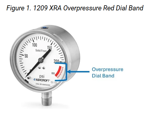
How operators know when the gauge is in the overpressure zone
A visual cue on the XRA dial helps operators recognize unsafe conditions and assess whether a different range or protection strategy is required. XRA gauges include a red dial band:
- The white measurement zone shows normal operating pressure.
- The red zone indicates the system has exceeded the gauge’s intended range.
How Does the 1209 XRA Gauge Perform Under Overpressure?
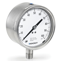
The Ashcroft?1209 Pressure Gauge is a solid front, stainless-steel pressure gauge designed for safety, durability and corrosion resistance. With the XRA option, it becomes a strong choice for processes with significant or unpredictable pressure excursions.
1209 XRA Key Features and Benefits
- Up to 417% overpressure protection
Survives severe pressure spikes without permanent damage, reducing downtime. - Solid-front case with full pressure-relief back
Directs energy away from the operator if a rupture occurs. - ±0.5% of span accuracy (ASME Grade 2A)
Supports precise readings in critical or high-value systems. - 4?-inch dial
Improves readability from longer distances. - Red overpressure dial band
Visually alerts operators to excursions beyond the rated range. - Optional PLUS!? Performance or liquid fill
Reduces pointer flutter in vibration-intense environments, improving readability and extending gauge life. - 316L stainless-steel construction
Provides strong corrosion resistance for harsh process conditions. - Welded socket-to-case design
Improves leak integrity where containment is essential.
Common 1209 XRA Overpressure Applications
- Oil & Gas: wellhead monitoring, injection skids, separator units
- Chemical Processing: corrosive media transfer lines, reactor feed systems
- Power Generation: boiler feedwater systems, auxiliary steam lines
- Pulp & Paper: digesters, bleaching systems, recovery operations
- Food & Beverage: high-pressure CIP systems, sterilization lines
- OEM Equipment: hydraulic power units, high-pressure pump skids
How Does the T6500 XRA Gauge Perform Under Overpressure?
The Ashcroft? T6500 XRA Pressure Gauge is a rugged, solid-front gauge designed for demanding process industries. When equipped with the XRA option, it provides durable and reliable performance in environments with vibration, weather exposure or mechanical shock.
T6500 XRA Key Features and Benefits
- Up to 400% overpressure protection
Allows the gauge to withstand severe and sudden surges in pressure. - Solid front case with full rear blowout back
Enhances operator safety by venting rupture energy away from the front. - ±1% accuracy standard; ±0.5% optional
Supports both general-purpose and higher-accuracy applications. - 100 mm or 160 mm dial options
Accommodates panel layouts, equipment size limitations and visibility needs. - IP66 / NEMA 4X protection
Enables use in washdown areas, outdoor installations and environments with dust or water exposure. - Optional PLUS!? Performance
Dampens vibration and pulsation for stable, readable measurements. - Stainless-steel case and wetted parts
Provides strong corrosion resistance suitable for most process environments. - Red overpressure dial band
Offers clear visual indication of pressure excursions. - Welded system design
Improves durability under high-cycle and high-vibration loading.
Common T6500 XRA Overpressure Applications
- Offshore Oil & Gas: mud pumps, choke/kill manifolds, stimulation equipment
- Chemical & Petrochemical: compressor discharge lines, reaction systems
- Power Generation: turbine lube oil systems, cooling water skids
- Pulp & Paper: washdown systems, digester feed lines
- Industrial Machinery: hydraulic presses, pump packages
- Food & Beverage: packaging equipment, washdown environments
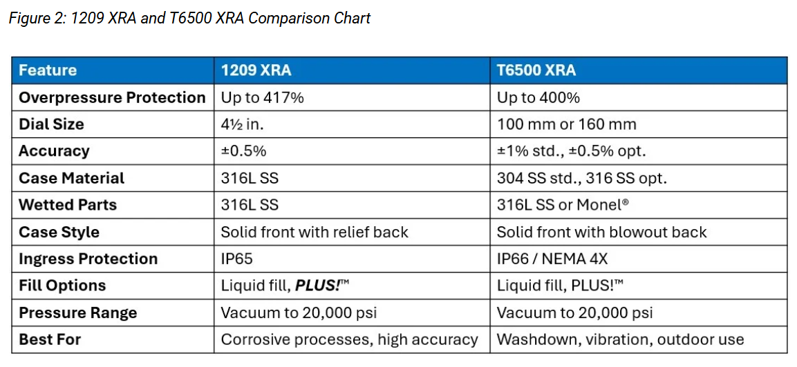
How to Choose the Right Overpressure Gauge for Your Application?
Both gauges provide strong protection against pressure spikes, extend instrument life and reduce the need for external protection devices.
You may prefer the 1209 XRA if you need:
- Superior corrosion resistance
- Standard high accuracy
- A stainless-steel case and wetted system throughout
You may prefer the T6500 XRA if you need:
- A rugged gauge for heavy vibration or outdoor conditions
- Flexibility in dial size and mounting options
Talk to one of our experts today at (855) 737-4714 or fill out our online form to learn more.
Ways to Calibrate a Pressure Transducer
Ashcroft
Across industries like manufacturing, energy, HVAC, and process control, accurate pressure measurement is critical to maintaining safety, efficiency, and product quality. Over time, even high-quality pressure transducers can experience drift — a gradual deviation between actual and measured pressure caused by vibration, temperature changes, or normal wear.
Calibration restores accuracy by comparing the transducer’s output to a known reference standard and adjusting as needed. But with multiple calibration methods available, the right approach depends on your environment, equipment and accuracy requirements.
As a recognized leader in pressure and temperature instrumentation, Ashcroft addresses this challenge with customers frequently. In this article, you’ll learn why pressure transducer calibration is essential, how zero and span adjustability preserve accuracy over time, the difference between primary and secondary calibration standards, and the lab and field methods that are best suited for both every day and hazardous applications.
Why calibrate a transducer?
Pressure transducers convert applied pressure into an electrical output signal. Over time, those signals can drift away from the true pressure reading due to mechanical stress or environmental factors.
Calibration verifies that the transducer’s output aligns with a known primary or secondary reference standard. If deviations are found, adjustments can be made to bring it back into specification.
According to the American Society of Mechanical Engineers (ASME), the reference instrument used for calibration should be at least four times more accurate than the device being tested. This guideline is often called the 4:1 rule. For example, a transducer rated at ±1% of full-scale accuracy should be calibrated using a standard accurate to ±0.25% or better.
Reasons to Calibrate:
- It's a new instrument that is not calibrated out of the box
- It's an instrument that has been repaired or modified
- The recommended usage or shelf life has elapsed
- A critical measurement is about to take place or has just complemented
- Whenever the instrument is exposed to an adverse condition like shock and vibration
- If observations are questionable
- When specified by a requirement, QA manual, customer specification or the manufacturer
What is zero and span adjustability in the calibration process?
A key part of any calibration process is knowing what’s actually being adjusted — the zero and span points that define accuracy.
Every pressure transducer has two critical reference points — zero and span:
- Zero offset is the output error at the low-pressure end of the range (or full vacuum for compound ranges)
- Span offset is the output error at the full-pressure end of the range
Over time, repeated pressure cycles, temperature changes, or component aging can cause drift at these endpoints. Zero and span adjustability allows users to correct those shifts, aligning the transducer’s output signal with the true pressure values without sending the unit back to the manufacturer.
Benefits of zero and span adjustability
- Field serviceability: Enables recalibration on-site, minimizing downtime
- Cost efficiency: Reduces the need for external recalibration service or sensor replacement
- Accuracy retention: Maintains reliable performance in demanding applications
However, while zero and span adjustments correct performance at the low and high ends of the range, but not necessarily in between them.
Now that we’ve defined what calibration adjusts, let’s look at how it can be done. Calibration methods generally fall into two categories — laboratory calibration for high accuracy and traceability and field calibration for quick verification and adjustment.
Primary and secondary calibration standards
Every calibration process relies on reference standards that define accuracy. These are classified as primary or secondary:
- Primary standards are the highest accuracy reference devices available. They establish pressure based on fundamental physical principles rather than a comparison. A deadweight tester is the best-known example of a primary pressure standard. Because it generates a known, traceable pressure, it’s used in laboratories to validate other instruments.
- Secondary standards are instruments that have been calibrated against a primary standard. They maintain high accuracy and are used to calibrate working instruments in both laboratory and field settings. Examples include digital test gauges and handheld calibrators.
Understanding how primary and secondary standards relate ensures your calibration process maintains a clear traceability path back to a national standard such as the National Institute of Standards and Technology (NIST), guaranteeing accuracy and compliance in your measurement records.
While calibration standards define the reference for accuracy, the calibration method describes how that reference is applied in practice. The following sections describe these methods in detail — from laboratory precision testing to field and hazardous-area calibration.
In the lab: manual calibration with a deadweight tester
Deadweight testers, like the Aschroft? Deadweight Tester 1305D, is considered the primary standard for pressure calibration and the best approach for high-precision verification. It operates on the fundamental principle that pressure is created by applying a known force over a specific area.
How it’s done:
- Connect the transducer and a reference gauge to the tester
- Apply known weights to generate pressure points across the measurement range
- Compare the transducer’s electrical output (voltage or current) with the reference readings
- Adjust zero and span until both match
This method delivers extremely high accuracy and traceability but requires controlled conditions, making it best suited for laboratory environments or when calibrating master reference instruments.
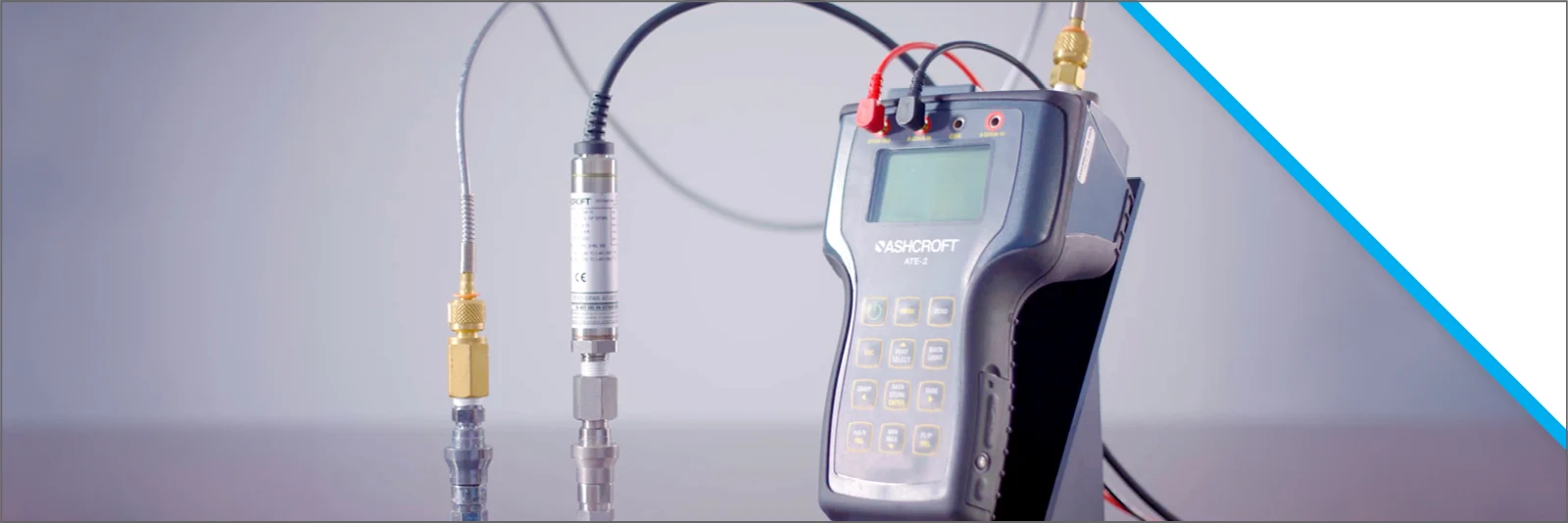
In the field: method using handheld or digital calibrators
When sending instruments to a lab isn’t practical, technicians can use portable instruments like the Ashcroft? ATE-2 Handheld Calibrator and Ashcroft's Digital Test Gauges to provide a versatile solution in the field for preventive maintenance, quick checks and on-site verification.
How it’s done:
- Connect the transducer and calibrator in a loop with a pressure source
- Apply pressure using a pump or regulator
- Compare the transducer output with the calibrator’s display
- Adjust zero and span either mechanically or through configuration software if the readings differ
This approach allows for regular field verification with good accuracy and minimal downtime — ideal for maintaining performance between lab calibrations.
Calibrating pressure transducers in hazardous areas
In industries such as oil and gas, chemical processing, or paint and coating, calibration often occurs in hazardous environments where explosive gases, vapors, or dusts are present. In these cases, transducers must be certified as explosion-proof (XP), intrinsically safe (IS), or non-incendive (NI) — each offering protection in a different way:
- Explosion-proof (XP): Contains any ignition within the housing
- Intrinsically safe (IS): Limits electrical energy to prevent sparks
- Non-incendive (NI): Restricts energy under normal conditions
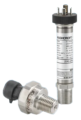
Traditional calibration methods that involve opening the housing or adjusting internal screws can’t be performed safely in these environments. To address this, the Ashcroft? E2S Intrinsically Safe Pressure Transducer and E2F Explosion Proof Pressure Transducers incorporate zero and span adjustability designed for hazardous areas.
Magnetic calibration with Ashcroft? pressure transducers
The Ashcroft? E2 Pressure Transducer Series features an external magnetic calibration system that allows users to perform precise zero and span adjustments without opening the housing. These options offer safe, efficient and repeatable field calibration in hazardous or outdoor applications.
How it works:
- The E2G includes an internal magnetic sensor that responds to a calibration magnet tool
- Holding the magnet near marked points on the housing engages calibration mode
- This allows zero and span corrections to be done quickly and safely - Watch video for details
Magnetic advantages
- Non-invasive: Preserves explosion-proof integrity and IP66/67 seal
- Fast: Calibration can be completed in minutes
- Safe: No tools or electrical exposure in hazardous areas
- Repeatable: Ensures long-term stability and SIL 3 safety compliance
When calibrating in hazardous zones be sure to only use approved magnetic tools and ensure all portable calibrators or power supplies are rated for the same hazardous area or isolated by barriers. To maintain certification compliance, always follow the manufacturer’s installation and safety documentation.
Regardless of the application, regular calibration ensures pressure transducers deliver consistent, reliable measurements throughout their service life. Understanding zero and span adjustability, along with the role of primary and secondary standards, helps determine the best method for maintaining accuracy.
Talk to one of our experts today at (855) 737-4714 or fill out our online form to learn more.
How Does Media Temperature Affect Pressure Transducer Performance?
Ashcroft
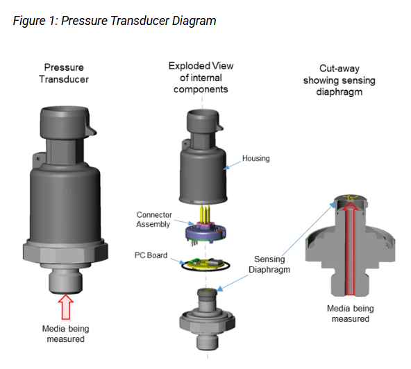
 When measuring pressure in challenging environments involving extreme temperatures, your instrument must perform accurately and reliably. Temperature exposure can come from many sources, including the process media and the ambient temperature surrounding the sensor. Each affects the transducer differently, but media temperature has the most direct impact because it acts on the sensing diaphragm and internal components. As media temperature rises or falls, it can distort readings, shorten sensor life or even damage components.
With more than 175 years of pressure and temperature measurement expertise, Ashcroft is recognized as an industry authority in helping customers maintain reliable measurement in even the harshest environments.
In this article, you’ll learn how process media temperature can impact pressure transducer performance, what causes output changes and how to minimize errors through proper design and installation. Understanding this information will help ensure you protect your instruments from performance drift or premature failure.
What is media temperature?
Media temperature refers to the temperature of the process fluid or gas that comes into contact with the sensing element of the pressure transducer. It is different from the ambient temperature, which affects the external housing and electronics. Both can influence performance, but media temperature typically has the greatest impact because it directly affects the sensing diaphragm and internal components.
As temperature changes, the materials inside the transducer—metals, adhesives, and fill fluids—expand or contract at different rates. This expansion and contraction can create stress on the sensing element, causing output changes even when pressure remains constant. If the temperature exceeds the transducer’s rated limit, it can permanently alter the properties of these materials and affect long-term performance.
How does temperature compensation work?
Temperature compensation works by using internal electronics to sense the device’s temperature and automatically adjust the measurement signal, reducing temperature-related errors. While this enhances accuracy, it is most effective when the entire pressure transducer remains at a uniform temperature. If parts of the transducer heat up or cool down at different rates—for example, during sudden changes in media temperature—uneven temperatures can cause temporary inaccuracies until the whole device reaches thermal equilibrium.
In applications where temperature changes slowly over several hours or days, the transducer is more likely to reach a stable temperature throughout, allowing compensation features to function optimally. However, in situations where media temperature shifts rapidly but the surrounding environment remains steady, targeted mitigation strategies are needed to address the resulting temperature effects on accuracy and stability.
How does temperature affect the mean time between failure?
Fluctuating or extreme temperatures can significantly impact instrument reliability. Temperature cycling introduces mechanical and electronic stress, while prolonged exposure to high operating temperatures is known to reduce the lifespan of electronic components.
To assess expected device longevity, Mean Time Between Failure (MTBF) calculations are commonly used; as a rule of thumb, MTBF typically decreases by half for every 10?°C increase in operating temperature. To enhance reliability and measurement accuracy, it is essential to implement solutions that bring equipment closer to ambient temperature conditions.
To mitigate the effects of temperature, you need to find a solution to make the equipment closer to ambient temperature, which will help with accuracy and reliability.
How to mitigate temperature effects
To protect your measurement instruments from damage, it’s important to ensure that the media temperature does not exceed the product’s specified operating range, which can happen when the transducer is mounted directly to a process line.
Several measurement instrument accessories are designed to help protect your instruments from this risk, including:
Capillary lines
Accessories like the Ashcroft? 1115 Capillary Line create physical distance between the process and the transducer, allowing you to mount the transducer in an area that is less exposed to extreme temperatures. One end of the capillary attaches to the process, while the other connects to the transducer. This arrangement keeps sensitive components away from potentially harmful process temperatures.
By reducing the amount of process media in the line and increasing the surface area exposed to ambient conditions, capillaries help bring the process media temperature closer to a safe operating range. Even a short length—just a few inches or centimeters—can make a significant difference in restoring media temperature to levels that are safe for the instrument (see Figure 2 below).
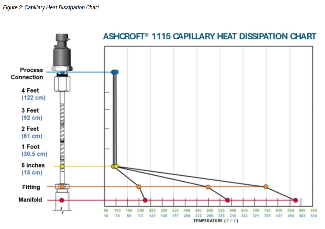
Capillaries work well in applications involving gases or liquids that are not expected to have rapid changes in pressure or large amounts of media flow in/out. When flow or rapid changes are expected, there are other solutions to consider.
Diaphragm Seals
Diaphragm seals are used to protect pressure transducers and other instruments when direct process compatibility is needed. They effectively seal and isolate the connection, preventing process media from entering the instrument while still allowing accurate pressure measurement.
It's important to note, however, that diaphragm seals can influence measurement accuracy because additional pressure is required to displace the fill fluid within the seal. This effect on accuracy is more pronounced with seals featuring higher spring rates, fill fluids with greater thermal expansion, and when used on lower-pressure range instruments.
To maintain reliable performance, it is considered best practice to recalibrate the pressure transducer with the diaphragm seal installed at the anticipated operating media temperature.
Steam Siphons
When measuring pressure in steam process lines, special considerations must be taken into account due to the significant energy carried by steam. Traditional accessories, such as extended capillaries, may not adequately reduce temperature because of the continuous movement of steam.
In these scenarios, steam siphons are specifically engineered to protect pressure transducers from elevated steam temperatures. By forming a condensate barrier, steam siphons shield the instrument from direct steam exposure and rapid temperature fluctuations, ensuring accurate measurements and extending the service life of the equipment.
Talk to one of our experts today at (855) 737-4714 or fill out our online form to learn more.
How To Properly Store Your Pressure Gauge
Ashcroft
 Pressure gauges are instruments designed to deliver reliable and accurate readings in demanding applications. Yet, even the most durable gauges can lose accuracy or fail prematurely if they aren’t stored correctly. Many issues that appear as calibration drift or pointer error actually begin long before the gauge is installed—during storage and handling.
As a trusted authority in pressure and temperature instrumentation for more than 170 years, Ashcroft has seen how improper storage can shorten the life of an otherwise high-quality gauge. In this article, you’ll learn how to properly store a pressure gauge, how environmental conditions affect performance, and what steps ensure your instruments remain ready for use.
Why is proper storage of your pressure gauge so important?
Pressure gauges depend on sensitive internal parts—like the Bourdon tube, movement, and pointer—to function accurately. When exposed to vibration, dust, moisture, or temperature extremes during storage, these components can degrade or shift out of calibration.
Proper storage helps you:
- Maintain gauge accuracy and calibration integrity
- Prevent corrosion or contamination
- Protect delicate mechanisms from mechanical damage
- Extend the gauge’s service life and reduce premature replacement
- Even if a gauge has never been used, improper storage can compromise its reliability once installed, leading to inaccurate readings or process safety risks.
What environmental conditions can affect a stored pressure gauge?
There are many environmental factors to consider when storing your pressure gauges. Three common conditions that require extra precaution during storage, include:
1. Temperature and humidity
Gauges should be stored in a dry, temperature-controlled environment. Humidity causes corrosion and condensation inside the case, while extreme temperatures can affect internal elasticity and fill fluid stability.
Keep the storage area between 40°F and 85°F (4°C–29°C) and maintain relative humidity below 85%.
If you must store gauges in unconditioned areas, seal them in plastic bags with a moisture-absorbing pack.
2. Dust and contaminants
Dust, debris, and airborne particles can clog the pressure connection or interfere with pointer movement. Store gauges in their original packaging or sealed containers to prevent exposure to contaminants.
3. Vibration and shock
Gauges are sensitive to impact. Place them on a padded, stable surface and avoid stacking heavy items on top. During storage or transport, keep them secure to minimize movement or vibration that could affect calibration.
Together, these environmental factors can gradually compromise a gauge’s performance long before it’s put into operation. By keeping instruments clean, dry, and protected from impact, you help preserve calibration integrity and extend service life—ensuring that each gauge performs as accurately in the field as it did when it left the factory.
Preparing pressure gauges for storage
Packaging plays an essential role in protecting pressure gauges during both shipping and long-term storage. Ashcroft gauges are packaged in durable cartons designed to minimize vibration, moisture exposure, and handling damage.
To maintain protection:
- Keep gauges in their original packaging until installation.
- Ensure protective caps remain on the pressure connections.
- Use foam or molded inserts if the original box isn’t available.
- Store cartons on shelves or pallets—never directly on damp floors.
If gauges will be stored for extended periods, place them in sealed plastic bags with desiccant packs to limit humidity exposure. Also, avoid storing gauges in direct sunlight or near heat sources, as UV exposure and temperature cycling can degrade dial markings and gaskets.
Can storage conditions affect pressure gauge accuracy?
Yes. Even when not in service, gauges can lose calibration if subjected to vibration, temperature variation, or improper storage orientation. Before reinstalling a stored gauge:
- Check that the pointer returns to zero at ambient pressure.
- Inspect the case and connection for corrosion or leaks.
- Verify the lens and fill fluid (if applicable) are clear and intact.
- Recalibrate gauges that have been stored for more than one year or under unknown conditions.
Most importantly, consider the calibration of your gauges throughout their storage period. Even when unused, gauges can drift over time due to material relaxation or environmental exposure. The frequency of recalibration depends on your process requirements, but it should be performed on a regular schedule.
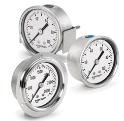
How do you store liquid-filled gauges?
Liquid-filled gauges are often used to dampen vibration and protect the internal mechanism, but the fill fluid (usually glycerin or silicone) is sensitive to temperature and position.
To store them properly:
- Keep them upright in a shaded, temperature-stable location.
- Avoid freezing temperatures, which can cause the fill fluid to expand and damage the lens.
- Do not expose to direct sunlight or heat sources.
- Wipe the case and window clean before packaging.
The most common fill fluids are glycerin, silicone, and halocarbon, but others may be used depending on the application. Each fluid type reacts differently to temperature changes—so understanding those limits is essential. For example, glycerin should never be exposed to temperatures below 0°F (-18°C), as it can freeze and damage the instrument.
If the fluid becomes cloudy or discolored, the gauge should be inspected before reuse—this can indicate contamination or seal degradation.
What is the best way to handle pressure gauges during storage transit?
Proper handling prevents mechanical damage that might not be visible until installation. Follow these guidelines:
- Handle gauges individually—never carry them by the connection threads.
- Avoid touching the dial face or pointer.
- Use protective caps on connections at all times.
- Store upright on shelves or racks, not loosely in bins.
- During shipment, use foam-lined or anti-vibration packaging to protect delicate internal components.
Talk to one of our experts today at (855) 737-4714 or fill out our online form to learn more.