Tips for Correctly Installing Pressure Gauges

WIKA
Tips for Correctly Installing Pressure Gauges from WIKA


Are your gauges installed properly? WIKA’s industry experts know that all too often this isn’t the case. Improperly installed gauges can lead to premature gauge failure and prevent you from troubleshooting issues with equipment or processes. Don’t let this happen at your plant. Use these six tips for proper gauge installation.

1. Select the Right Gauge

Before you pull out a wrench, first make sure you have the right type of gauge for the application. The pressure gauge you choose must be the correct one for the:

  • Expected pressure range to be measured. The selected range should be double the operating range.
  • Process media compatibility.
  • Process temperature
  • Severe operating conditions (e.g., vibrations, pulsations, pressure spikes).

However, even if you install the gauge perfectly, you could face the same problems you had before the installation if the gauge isn’t the right one for the job.

2. Apply Force on Wrench Flats

Once you’ve chosen the correct gauge, pay attention to how you install the gauge. Rather than turning the case by hand, use an open-end wrench and apply force to the wrench flat. Applying the force through the case could damage the case connection as well as the gauge internals. Not applying sufficient torque could result in leaks.

3. Seal the Deal

Notice the type of threads on the gauge before you seal it. If the gauge has parallel threads, seal it using sealing rings, washers, or WIKA sealing rings (crush rings). If the gauge has tapered threads, additional means of sealing, such as PTFE tape, are recommended. This is standard practice for any pipe fitter because tapered threads do not provide complete sealing on their own.

4. Use a Clamp Socket or Union Nut with Straight Thread

When tapered threads are used, the installer has the luxury of adjusting the gauge even after sufficient torque has been applied. This allows for convenient orientation of the gauge face. However, with straight threads, the face orientation is not adjustable once it bottoms out. For that reason, we recommend using WIKA sealing rings (crush rings) instead of flat washers. The WIKA sealing ring allows you to correctly orient the gauge after the socket has been seated on the sealing ring. You start by tightening the gauge by hand. As soon as you encounter a resistance, apply an open-end wrench to the wrench flat and continue turning the gauge. At this point, you have approximately one turn left to put the gauge into the desired position.

5. Leave Space for Blow-out

For personnel safety, some gauges come with a safety pattern design consisting of a solid wall between the front of the gauge and the Bourdon tube, and a blow-out back. In the event of a pressure build-up inside the case or a catastrophic Bourdon tube rupture, all the energy and release of media will be directed to the back of the gauge, thus protecting the people reading the gauge. In order for the safety device to function properly, it is important to keep a minimum space of 1/2 inches. WIKA XSEL? process gauges come standard with integrated pegs to ensure this distance when mounting the gauge against a surface.

6. Vent the Gauge Case

Some gauges come with a small valve on top of the case. Users who don’t understand the purpose of the valve are confused about why it’s included. During shipment, liquid-filled gauges can go through temperature changes that create internal pressure build-up. This can cause the gauge pointer to be off zero. When installing the gauge, open the compensation valve to allow this pressure to vent. It should then be closed again to prevent any external ingress. After you mount the gauge, set the compensating valve from CLOSE to OPEN.

A pressure gauge can do its job only if it’s installed properly. Whether you’re an operator or a maintenance technician, use these tips for proper gauge installation to make sure your gauges perform as they should.

Talk to one of our experts today at (855) 737-4714, or fill out our online form to learn more. 

8 Common Reasons For Pressure Gauge Failure

WIKA

Pressure gauges are an integral part of an application’s warning system. By constantly measuring pressure, these instruments allow users to see how a process is doing. Gauges are sturdy and can handle challenging conditions. However, even the toughest instruments will experience failure if they weren’t designed for a specific application or condition.

At WIKA USA, our customers often ask us why their gauges are damaged or stopped working properly. With decades of pressure experience, we have seen all the causes of pressure gauge failure.
 

diagram of a bourdon tube pressure gaugeHow A Pressure Gauge Works

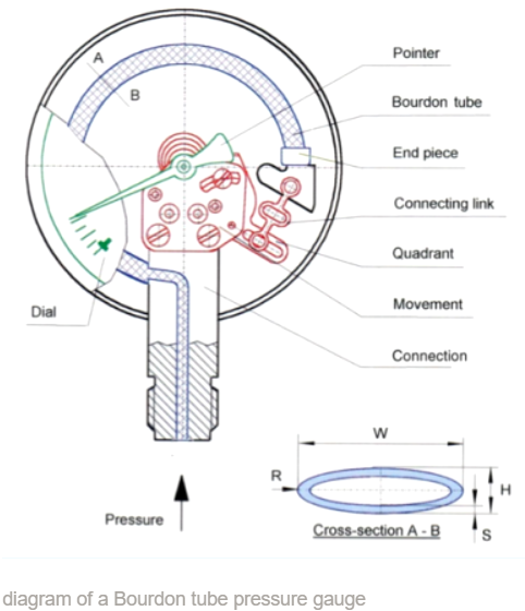
Before getting into why things go wrong and how to troubleshoot the problem, it’s important to first understand the inner workings of a mechanical gauge, the most popular of which is the Bourdon tube pressure gauge.

The Bourdon tube is a hollow C-shaped spring element within the case. As the tube is pressurized from the media entering it, it starts to move – like a balloon trying to equalize. This movement is translated through the connecting link, attached to the Bourdon tube via the end piece, into a pressure measurement that the pointer indicates on the dial.
 

8 Causes of Gauges Failure

When a pressure gauge doesn’t work as expected, the cause can be traced back to at least one of these eight reasons:


1. Mechanical vibration

Numerous studies have shown that vibration is the main cause of pressure gauge failure in manufacturing facilities. Vibration has a negative impact on gauge accuracy in two ways. First, it is difficult to read the pointer on a dial when a gauge is vibrating. Second, incremental damage to the pointer mechanism from vibration can eventually move a pointer off zero, producing inaccurate readings.

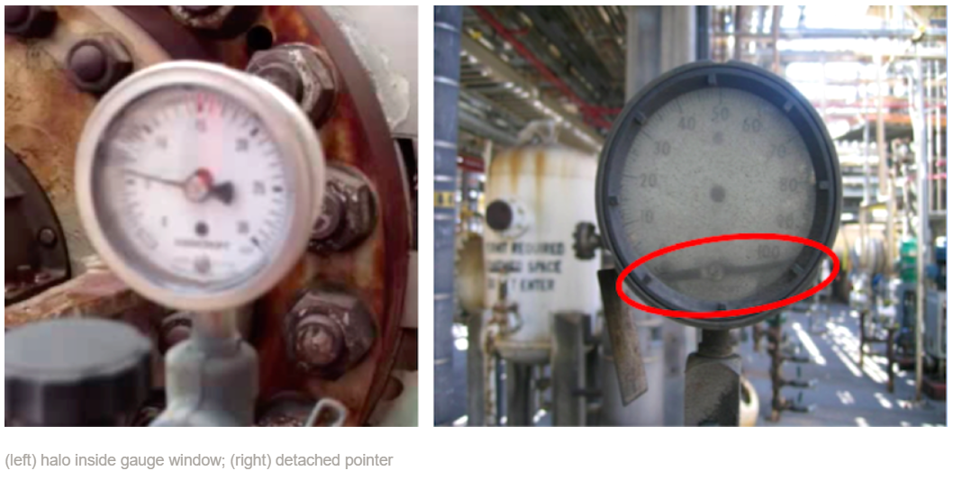
Visible signs of mechanical vibration

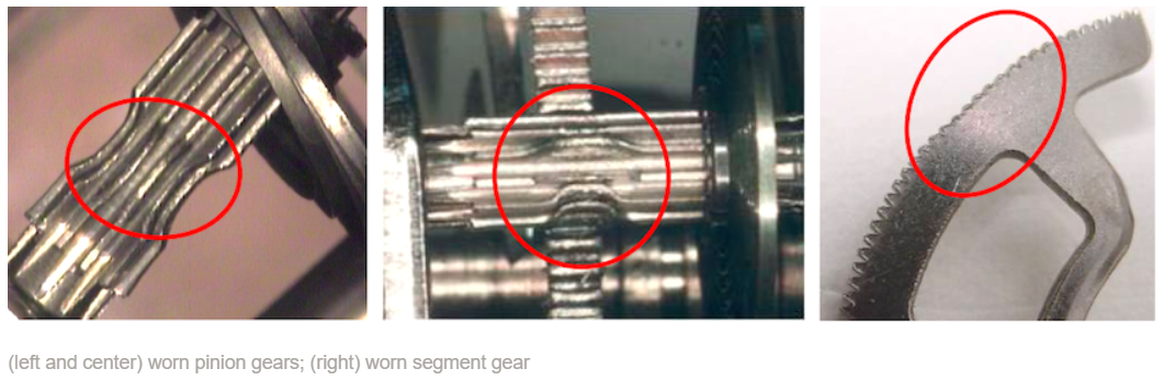
  • Metal filings/dust, like a halo, inside the gauge window from worn pinion and segments gears
  • Detached pointer if the vibration is severe
halo inside gauge window, detached pointer


Risks posed by mechanical vibration

  • Wear and tear of internal components
  • Loss of accuracy/functionality
  • Pressure system failure
     
worn pinion gear; worn segment gear


Solutions for gauges experiencing mechanical vibration

model 990.28 diaphragm sealFor most situations, a liquid-filled case is the most convenient and cost-effective way to protect pressure gauges from vibration. The glycerin or silicone-oil case fill acts as a damper to slow down the movement. It also lubricates the pinion and segment gears, thereby reducing wear and prolonging the life of a gauge.

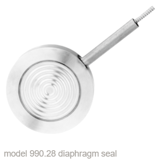
A second solution is to move the gauge away from the source of the vibration. How? Use a diaphragm seal with capillary connection, like the 990.28 cell-type (sandwich) seal. A diaphragm seal can be mounted practically anywhere in the application, and the line allows for remote reading. (See this video and blog for more info on how diaphragm seals work.)


2. Pulsation

pointer fultterVibration refers to regular oscillation of mechanical parts. Pulsation, on the other hand, is regular instances of rapid pressure increases and decreases of the media.

Visible signs of pulsation
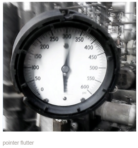
  • Pointer flutter
  • Loose or broken pointer in extreme cases

Risks posed by pulsation

  • Difficulty in obtaining an accurate reading
  • Wear and tear of internal components
  • Loss of accuracy/functionality
  • Pressure system failure

Solutions for gauges experiencing pulsation

As with mechanical vibration, a liquid-filled case is an easy solution. So are valves and protective devices like a socket restrictor. This small device has a small orifice to restrict and slow down the pressure of the media before it encounters the gauge. Restrictors are cost-effective and easy to install. Several gauges, like model 111.11 for compressed gas regulators, come standard with a restrictor already threaded into the bore.

For more extreme pulsation, use a snubber or needle valve. Snubbers function like restrictors but come in more material choices, orifice sizes, and psi ratings. Snubbers are also less prone to clogging and are more adjustable in the field, thanks to interchangeable pistons or adjustment screws. Needle valves also throttle the media, thereby reducing the impact of pulsations. These pulsation dampeners are commonly found in pump discharge and boiler house applications.


3. Extreme temperature

gauge discolorationDifferent gauges have different tolerances for extreme temperatures. We look at both ambient temperatures, such as what is found in the Arctic or around a furnace, and the temperature of the process media.

Visible signs of extreme temperature

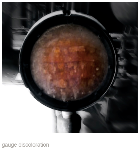
  • Dial and/or liquid fill is discolored, usually yellow, orange, brown, or black
  • Dial, case, or window is melted – usually because the media is too hot

Risks posed by extreme temperature

  • Difficulty in obtaining an accurate reading
  • Loss of accuracy/functionality
  • Pressure system failure

Solutions for gauges in extreme temperatures

model 910.32.250 mini cooling adapter
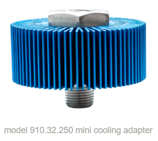
A diaphragm seal with capillary allows pressure measurement to occur away from extreme ambient or media temperatures. The longer the run, the more heat is dissipated before the pressure reaches the gauge. Or attach a cooling adapter like the 910.32.200 (up to 500°F/260°C) or 910.32.250 (up to 700°F/370°C). With fins to increase the surface area, these adapters are very effective at radiating and dissipating heat. They’re also extremely easy to retrofit using threaded connections. Pigtail, coil, and mini (rod and cap) siphons use the same principle to dissipate heat.

Glycerin is the typical fill fluid for pressure gauges. For extremely hot or cold ambient temperatures, silicone oil is the better choice as it will not discolor in heat over time or freeze in sub-zero environments.


4. Pressure spikes

Spikes occur when the pressure sharply increases and then suddenly drops. This condition can cause all sorts of problems for gauges not designed for this condition.

bent pointerVisible signs of pressure spikes

  • Bent pointer, like a fishtail or fish hook, from hitting the stop pin too often
  • Nicked or broken pointer from hitting the stop pin too hard
  • Broken stop pin

Risks posed by pressure spikes

  • Increased wear on movement and components
  • Loss of accuracy/functionality
  • Split Bourdon tube, leading to released media
  • Pressure system failure

Solutions for gauges experiencing pressure spikes

As with pulsation, good solutions for dampening the effects of pressure spikes are to use a liquid-filled gauge and/or accessories like restrictors, snubbers, needle valves, or diaphragm seal with capillary. Another way to prevent damaged pointers and internals is to replace the gauge with one that has a higher pressure range. A good rule of thumb is to choose a gauge that is two times the expected pressure maximum. So, if a process typically reaches 500 psi, use one that goes up to 1,000 psi.

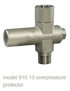
For greater reassurance that a gauge never exceeds a certain maximum, attach an overpressure protector to the instrument. This unique option allows the user to changing the maximum pressure setting. If the pressure ever reaches that value, the protector’s spring-loaded piston valve will automatically close, preventing the gauge from experiencing the spike. And when the system pressure drops approximately 25% below pre-set maximum, the valve with automatically reopen.


pointer buried against stop pin5. Overpressure

This situation is very similar to pressure spikes, but occurs when the gauge regularly measures pressures near or at the maximum range. We typically see this condition in water/wastewater treatment and gas lines.

Overpressure can cause the Bourdon tube to deform and split. This is major problem because a rupture allows caustic media, such as the hydrofluoric (HF) acid in alkylation units, to escape. In pharmaceutical manufacturing, a rupture event ruins very expensive product and leads to shutting down the line, quarantining the product, and re-sterilizing the process.

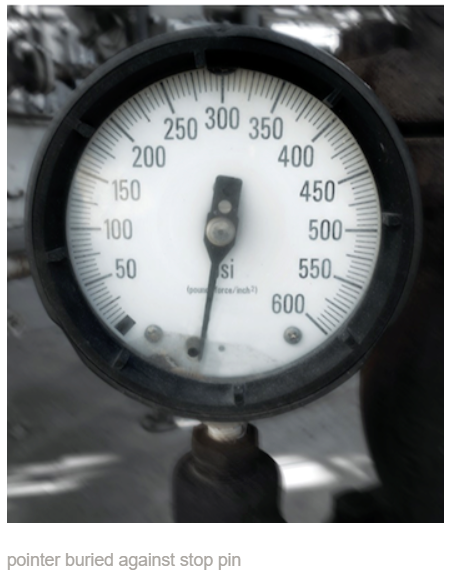
Visible signs of overpressure

  • Pointer buried against stop pin
  • Pointer dislodges stop pin

Risks posed by overpressure

  • Increased wear on movement and components
  • Loss of accuracy/functionality
  • Split Bourdon tube, leading to released media
  • Pressure system failure

model 910.13 overpressure protectorSolutions for gauges experiencing overpressure

As overpressure is similar to pressure spikes, so is the fix: use a gauge with a higher pressure range, and attach an overpressure protector.


6. Corrosion

Many industries work with harsh chemicals: hydrofluoric acid in refineries, flocculants and chlorine in wastewater treatment, chlorinated gases in fiber optic production, and so on. These media find their way into gauges.

corroded pressure gaugeVisible sign of corrosion

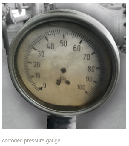
  • Discoloration and deterioration of the gauge case, pointer, connection, and dial

Risks posed by corrosion

  • Loss of accuracy/functionality
  • Pressure system failure

Solutions for gauges in corrosive environments

Isolate the gauge from harsh chemicals by using a diaphragm seal made of the appropriate corrosion-resistant materials. WIKA’s diaphragm seals come in a variety of standard and exotic alloys for both the wetted and non-wetted parts: 316L and 316 TI stainless steels, Hastelloy?, Monel?, Inconel?, tantalum, and titanium. The metals can be left as-is or, for extra protection, lined with Teflon? or plated with gold. When deciding on the materials for your diaphragm seals, look at what the existing wetted parts are made of, and choose those.
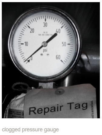

clogged pressure gauge7. Clogging

Clogging is an issue for paper plants, wastewater plants, pharmaceuticals, and other industries, as slurry, pulpy, viscous, and high-particulate media can gum up the system.

Visible sign of clogging

  • Gauge at or near zero when the system is operating

Risks posed by clogging

  • Loss of accuracy/functionality
  • Possibility of overpressure

Solutions for gauges measuring clogging media

Again, use a diaphragm seal to separate the gauge from the challenging media. An excellent solution is WIKA’s All-Welded System (AWS), an assembly comprising an XSEL? industrial process gauge permanently welded to a bell-shaped diaphragm seal.

As the AWS still has a small orifice that the media can enter, customers can opt for versions with a flushing port. This component allows operators to clear away media either when clogging occurs or during regular maintenance.

Another solution is WIKA’s INLINE? diaphragm seals, which has smooth walls for full flow-through. By eliminating dead spaces, there’s no risk of media buildup.
 

8. Mishandling/abuse

Gauges look sturdy, especially the larger process gauges, but they are not designed to be handles or footholds! During site visits, we often see evidence of gauge mistreatment. Operators might grab on to a gauge as they move around process skids on wheels, or step on them as they climb scaffolding. Not only is this practice unsafe, it increases the chances of gauge damage and failure.

pressure gauges with broken window and cracked case

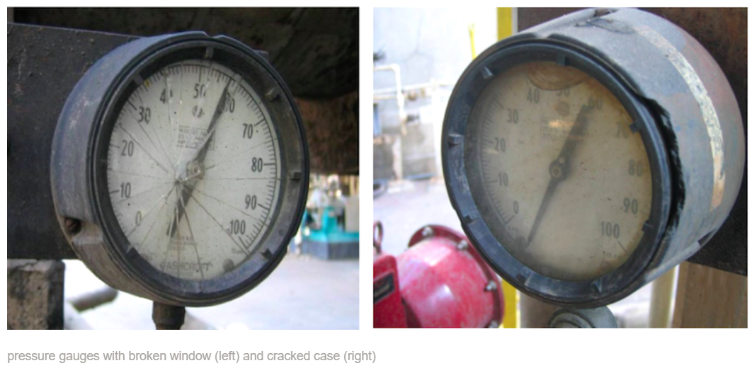
Visible signs of mishandling/abuse

  • Cracked case
  • Broken window
  • Loss of case filling
  • Crooked or bent gauge and/or process connection

Risks posed by mishandling/abuse

  • Loss of functionality

Solutions for gauge mishandling/abuse

Training is the best prevention. Employees should be aware of the dangers of mishandling gauges. They should also know how to properly connect gauges. For example, when threading the gauge onto the process, some people tighten it by hand, which risks torquing the case. When the NPT or G connection has a wrench flat area, use a wrench to tighten the gauge.

WIKA USA’s pressure specialists have decades of experience diagnosing why gauges fail, and then coming up with solutions so that instruments last longer. When the causes aren’t obvious, we encourage customers to take advantage of our Instrument Failure Analysis (IFA) program. Send the failed gauge to our facilities in Lawrenceville, Georgia, and our engineers will conduct a full evaluation on the nonfunctioning gauge – all free of charge. Contact WIKA USA for more information about why pressure gauges fail and what you can do to solve the problem.

Talk to one of our experts today at (855) 737-4714, or fill out our online form to learn more.

Pt100 and Pt1000 Sensors: Important Facts and Differences

WIKA

WIKA Pt100 and Pt1000 Sensor
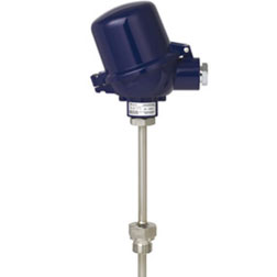
Resistance temperature detectors (RTDs), also called resistance thermometers, are popular temperature measurement devices due to their reliability, accuracy, versatility, repeatability, and ease of installation.

The basic principle of an RTD is that its wire sensor – made of a metal with a known electrical resistance – changes its resistance value as the temperature rises or falls. Although resistance thermometers have certain limitations, including a maximum measuring temperature of about 1,100°F (600°C), overall they are the ideal temperature measurement solution for a multitude of processes.

Why Use a Platinum Sensor

The sensing wires in an RTD can be made of nickel, copper, or tungsten, but platinum (Pt) is by far the most popular metal used today. It’s more expensive than other materials, but platinum has several characteristics that make it particularly well-suited for temperature measurements, including:

  • Almost linear temperature–resistance relationship
  • High resistivity (59 Ω/cmf compared to 36 Ω/cmf for nickel)
  • Non-degradable electrical resistance over time
  • Excellent stability
  • Very good chemical passivity
  • High resistance to contamination

To learn more about the relation between temperature and resistance in platinum RTD sensors, download the WIKA temperature table.

The Difference Between Pt100 and Pt1000 Sensors

Among platinum RTD sensors, Pt100 and Pt1000 are the most common. Pt100 sensors have a nominal resistance of 100Ω at ice point (0°C). Pt1000 sensors’ nominal resistance at 0°C is 1,000Ω. Linearity of the characteristic curve, operating temperature range, and response time are the same for both. The temperature coefficient of resistance is also the same.

However, due to the different nominal resistance, readings for Pt1000 sensors are higher by a factor of 10 compared to Pt100 sensors. This difference becomes evident when comparing 2-wire configurations, where lead measurement error is applicable. For instance, the measurement error in a Pt100 could be +1.0°C, and in the same design a Pt1000 could be +0.1°C.

How to Choose the Right Platinum Sensor

Both types of sensors work well in 3- and 4-wire configurations, where the additional wires and connectors compensate for the effects of the resistance of the lead wires on the temperature measurement. The two types are also similarly priced. Pt100 sensors, however, are more popular than the Pt1000 for a couple of reasons:

  • A Pt100 sensor comes in both wire-wound and thin-film constructions, offering users choice and flexibility. Pt1000 RTDs are almost always only thin-film.
  • Because their use is so widespread across industries, Pt100 RTDs are compatible with a large range of instruments and processes.

So, why would someone opt for the Pt1000 sensor instead? Here are the situations where the greater nominal resistance has the clear advantage:

  • A Pt1000 sensor is better in 2-wire configurations and when used with longer lead wire lengths. The fewer the number of wires and the longer they are, the more resistance is added to the readings, thereby causing inaccuracies. The Pt1000 sensor’s greater nominal resistance compensates for these added errors.
  • A Pt1000 sensor is better for battery-operated applications. A sensor with a higher nominal resistance uses less electrical current and, therefore, requires less power to operate. Lower power consumption extends battery life and the interval between maintenance, reducing downtime and costs.
  • Since a Pt1000 sensor uses less power, there is less self-heating. This means fewer errors in the reading as a result of higher-than-ambient temperatures.

In general, Pt100 temperature sensors are more commonly found in process applications, while Pt1000 sensors are used in refrigeration, heating, ventilation, automotive, and machine building applications.

Replacing RTDs: A Note About Industrial Standards

RTDs are easy to replace, but it’s not a matter of simply swapping one for another. The issue that users must watch out for when replacing existing Pt100 and Pt1000 sensors is the regional or international standard.

The older U.S. standard states platinum’s temperature coefficient as 0.00392 Ω/Ω/°C (ohm per ohm per degree centigrade). In the newer European DIN/IEC 60751 standard, which is also used in North America, it’s 0.00385 Ω/Ω/°C. The difference is negligible at lower temperatures, but becomes noticeable at the boiling point (100°C), when the older standard will read 139.2Ω while the newer standard will read 138.5Ω.

Talk to one of our experts today at (855) 737-4714, or fill out our online form to learn more.

Have You Integrated Your Z and Theta Motions Into One Compact Actuator?

Corey Foster || Valin Corporation

 PPH Integrated Z-Theta Picker Head Actuator from PBA SystemsMotion architecture may look fine on paper until the cycle rate increases, the available space shrinks, and the “simple” pick-and-place head becomes far more complicated than expected. That is often when the real cost of stacking separate axes becomes clear: a Z stage here, a rotary stage there, more cabling, more alignment work, and more opportunities for drift over time.

That is why integrated solutions like the PPH Integrated Z-Theta Picker Head Actuator from PBA Systems deserve serious consideration. This compact motion actuator combines vertical Z-axis travel and rotary theta motion in one unit, built specifically for high-speed, high-precision automation environments.


The problem with traditional Z + rotary stacks in pick-and-place systems

In many semiconductor and SMT machines, the picker head is doing two jobs at once:

  • moving up and down rapidly (Z-axis motion)
  • rotating for alignment (Theta-axis motion)

The traditional approach is to bolt together multiple stages. And that approach works… until performance limits are pushed. The more axes that are stacked, the more the system introduces:

  • extra height in the machine
  • mechanical tolerance buildup
  • alignment challenges
  • tuning complexity
  • long-term maintenance concerns

In space-constrained automation, these compromises show up quickly.


A compact integrated Z-Theta actuator: what the PPH does differently

The PPH actuator integrates Z and Theta motion into a single compact 15 mm body, immediately simplifying picker head architecture. Instead of coordinating separate actuators, machine builders gain one clean module designed for:

  • high-speed pick-and-place
  • precision alignment
  • tight machine envelopes
  • scalable multi-head configurations

This type of integration decision often makes the rest of the machine easier to design, assemble, and support.


Precision performance that matters in production

Specifications only matter if they hold up in real automation environments.

The PPH platform is built around the motion performance required for semiconductor handling and micro-component placement:

  • 0.1 μm resolution
  • ±0.5 μm repeatability on the Z-axis
  • Theta repeatability of ±0.005°
  • Rotary speeds up to 3,000 RPM (page 2 technical specifications)

That level of control is essential when placing components that do not tolerate positioning errors.
 

Force-controlled soft landing: an underrated feature

One of the most valuable aspects of this actuator is not only speed, but controlled contact. The PPH supports force-controlled soft landing, allowing the head to approach quickly and then land gently.

In practical terms, this provides:

  • reduced part damage
  • improved yield
  • more consistent handling
  • higher throughput without excessive force

This capability is especially important in:

  • semiconductor pick-and-place
  • LED sorting
  • delicate inspection workflows (page 2 highlights this throughput advantage)


Designed for scalable multi-head automation

Many high-volume production machines do not stop at one picker.

PBA designed the PPH platform to scale from:

  • a single pick head
  • to multi-head arrays (10+ heads)

The system also supports:

  • embedded encoder feedback
  • vacuum suction integration
  • modular configurations for production equipment (page 1 product benefits and features)

This flexibility matters when automation platforms must evolve across multiple machine generations.


Where integrated Z-Theta motion is most valuable

The datasheet identifies several environments where compact Z-Theta actuators provide major benefits:

  • semiconductor automation and component pick-and-place
  • SMT and PCB surface mount equipment
  • automated optical inspection (AOI)
  • LED and micro-part sorting
  • precision Z-Theta alignment stations (page 1 applications list)

These are industries where motion performance is not a luxury — it defines the machine.


Closing thought: integration is often the real performance upgrade

In many automation systems, the limiting factor is not the motor or controller. It is the mechanical stack-up.


When axes are integrated cleanly, the system does not just save space — it reduces the number of places where compliance, drift, and accumulated error can enter.

The PPH Integrated Z-Theta Picker Head Actuator is a strong example of that philosophy: compact, precise, scalable, and designed for automation environments where motion truly makes the difference.


Talk with Valin about high-speed pick-and-place motion

If a semiconductor, SMT, or inspection system requires compact Z-Theta actuator integration, Valin’s automation team can support configuration selection, sizing, and application engineering.


Talk to one of our experts today at (855) 737-4716 or fill out our online form to learn more. 

Using a Differential Pressure Transmitter for Liquid Measurement

WIKA

The market offers several methods for measuring and monitoring liquid levels. For closed vessels, operators commonly choose a differential pressure transmitter. This is a proven technique, especially when the measuring instrument should not be immersed in the media, such as for tanks that have a grinder or hold aggressive substances. However, if the application requires high accuracy, this method of level measurement soon comes up against its limits.

Before making the case for using two interconnected process transmitters rather than other configurations or instruments, let’s take a look at what a differential pressure transmitter is and how this pressure instrument measures liquid levels.

How differential pressure transmitters work
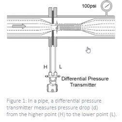
What Differential Pressure Transmitters Do

A differential pressure transmitter measures and calculates the difference between two points of pressures, and sends that information via a signal to a programmable logic computer (PLC).

These sensors were originally designed for use in pipes to measure pressure before and after the fluid encounters a filter, pump, or another interruption in flow. Standard differential pressure transmitters come with two process connections arranged side by side to measure the drop in pressure (d) between the higher and lower points (H and L, respectively, in Figure 1). Classic differential pressure transmitters can also measure flow rates.

It wasn’t long before people realized that differential pressure measurements could be used to determine liquid level as well.

Measuring Level with a Differential Pressure Transmitter: Advantages and Challenges

Level Measurement with a Differential Pressure Transmitter
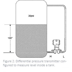
A differential pressure transmitter calculates level by measuring the differential pressure between the liquid and the gaseous phases of the fluid inside a closed tank. For precise calculations, important factors include:

  • Geometry of the tank (horizontal or vertical, shapes of various lids and bottoms, etc.)
  • Specific density of the medium
  • Hydrostatic pressure

The distance between points H and L in a tank is necessarily much longer than in a pipeline, necessitating the use of tubing to bridge that distance (Figure 2: Differential pressure transmitter configured to measure level inside a tank). But not just any size of tube will do. For accurate measurements, these small pipes – capillaries, really – have to be so thin and limited in volume that they transmit media without any changes in pressure.

However, using capillaries creates its own set of challenges. Within an enclosed system, the pressure of a gas is directly proportional to its temperature. This is Gay-Lussac’s Law. In larger pipes, an increase in temperature/pressure won’t have much effect on differential pressure readings. But within the confines of a capillary, any changes in temperature and, thus, pressure are magnified. Measurement solutions with this kind of connection to the measuring points are sensitive to temperature. In the worst-case scenario, severe fluctuations could result in falsely measured values.

Talk to one of our experts today at (855) 737-4714, or fill out our online form to learn more. 

Introduction to Differential Pressure Measurement

WIKA

By measuring differential pressure, users are able to easily and accurately monitor filter conditions, liquid levels in closed tanks, liquid flow rates inside a pipe, and even the output torque of hydraulic motors.

There are three methods of measuring pressure. The most common type of pressure measurement is gauge pressure, with reference to atmospheric pressure. This is any pressure applied to the system on top of atmospheric pressure, also known as ambient pressure. A prime example of gauge pressure measurement is a car’s tire pressure.

Absolute pressure, with reference to a full vacuum, measures pressure independently of changes in atmospheric pressure. Absolute pressure measurement is used in applications where it is critical to monitor the peak of a vacuum, and is needed in laboratories, meteorology, aviation, and other fields.

Basics of Differential Pressure and DP Gauges

WIKA Differential Pressure Δp = p1 – p2
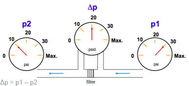
Differential pressure – the third method of measuring pressure – is simply the difference between two applied pressures, often referred to as delta p (Δp). In the example, Δp = p1 – p2.

But why even use a differential pressure (DP) gauge? Why not just place a standard pressure gauge at the p1 and p2 measurement locations, and then have a technician work out the difference? Besides the extra time and effort required for manual calculations, a DP gauge is superior for several reasons:

  • Sensitivity. Differential pressure gauges are designed to detect minute differences that the human eye cannot see. As an example, let’s put two standard gauges on either side of a filter. Both pointers might indicate 100 psi, but a DP gauge would be sensitive enough to pick up a difference of as low as 10″ H2O (inches water column), or 0.36 psi. A differential pressure gauge indicates only the Δp; it basically eliminates all the unnecessary “noise.”
  • Range. The range of a differential pressure gauge can go as low as 0.2″ H2O for air handling systems and as high as 15,000 psi with a Bourdon tube DP gauge. Even at very low differential pressure ranges, the DP gauge must be rugged enough to withstand very high working pressures.
  • Working pressure. Besides the differential pressure range, the maximum working pressure is very critical. Without knowing the working pressure, we cannot determine the correct DP gauge for the application. The working pressure in almost every DP application is significantly higher than the actual DP range.
  • Options. Differential applications often require different pressure port positions, additional pressure ports, and different process connections than the typical ?” or ?” NPT male thread used on standard gauges. For liquid level measurements, a combined top/bottom connection (total of four pressure ports) in combination with a ?” NPT female thread can be the norm. For filter applications, in-line connections (also known as end connections) are typical, and to measure the low pressure in air handling systems, a hose barb connection is the one most often used.

There are also many options for units of measurement other than just psi, bar, and inches of water column. If measuring content in liquid level applications, users can choose among scales that read in pounds, kilograms, or gallons. In flow applications, differential pressure gauges often read in SCFM (standard cubic feet per minute), GPM (gallons per minute), m3/s (cubic meters per second), etc. And in aviation, using pitot tubes, a differential pressure gauge measures airspeed in knots or miles.

Four Applications for Differential Pressure Measurement

Differential pressure measurement goes beyond regular pressure measuring. Indeed, this type of pressure measurement is the means by which many industries monitor filter conditions, liquid level, liquid flow rate, and torque output.

1. Filter monitoring

WIKA Model 700.04 Differential Pressure gaugeThis is the most common application for differential pressure measurement, used in industrial oil filter applications, air filter monitoring in gas turbines, and filter monitoring – such as membrane sensing – in water/wastewater facilities. DP gauges for these industries include models 700.04, 732.25, and 732.51. To detect very low pressure in commercial and industrial HVAC systems, products in WIKA’s air2guide series, such as the A2G-10, are excellent options, as is the 716.11.

As the filter becomes clogged, the differential pressure increases. For extra convenience and performance, choose a DP gauge with an output signal, like the A2G-15, to remotely monitor the status of a filter.

2. Liquid level measurement

Liquid level measurement using a DP gauge
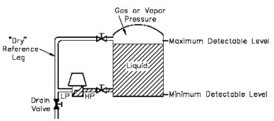
In an open vessel where nothing is pressurized, a simple pressure gauge is sufficient for calculating the liquid level. But in a sealed tank with liquid and gas phases, the only way to monitor that liquid level is to deduct the low-pressure side (gas or vapor) from the high-pressure side (liquid).

WIKA has about a dozen technologies for measuring tank level. The choices include the Cryo Gauge for liquid gas tanks, which can be accessorized with liquid-level and working-pressure transmitters for using the output signal in a telemetry system. A telemetry device is used to remotely monitor your customer’s tank level and to deploy a refill as needed.

3. Flow measurement

WIKA FlowPak flow meter
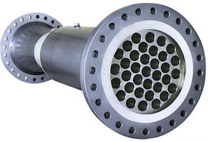
A primary flow element, such as an orifice plate, flow nozzle, Venturi tube, Venturi nozzle, or our high-accuracy FlowPak (FLC-HHR-FP), creates a constriction from a larger upstream diameter (point 1) to a smaller downstream diameter (point 2). This constriction in a pipe causes a pressure drop that is proportional to the square of the flow rate. Using Bernoulli’s equation, one can relate the differential pressure of the fluid with its flow velocity. Thus, the combination of a differential pressure gauge and a primary flow element creates a reliable flow meter.

4. Drill head monitoring

In hydraulic systems, a Bourdon tube-type DP gauge can be used for measuring the output torque of positive displacement motors. The gauge measures the pressure drop of the motor powering the gearbox by simultaneously measuring the pressure on the pressure and return sides of equipment during operation. By measuring the pressure drop, the DP gauge calculates the amount of torque that the hydraulic motor generates.

How to Select a Differential Pressure Gauge

Similar to selecting a standard pressure gauge, several criteria go into the selection of a DP gauge. Here are some questions to ask when choosing a differential pressure gauge:

  1. What differential pressure range does the application call for? This is the pressure difference that you want the scale to read.
  2. What is the maximum working pressure of the process? This is the maximum pressure at which the system is capable of operating for a sustained period.
  3. What media will the wetted parts come into contact with? The wetted parts of a regular gauge are basically just the Bourdon tube and process connection. A differential pressure gauge sometimes has two chambers; in one chamber, more parts – the movement, pointer, dial, window, and gasket – might come into contact with the media. Corrosive media might require stainless steel or a special material.
  4. What is the application? The choice of DP gauge often depends on whether it is used for filter monitoring, liquid level measurement, flow measurement, or drill head monitoring.
  5. Are there any special requirements? WIKA manufactures DP gauges for specific industries, such as NACE-compliant gauges for sour gas (hydrogen sulfide) service or gauges cleaned for oxygen service.
  6. What type of mounting will the gauge need? Mounting can be very specific to the industry. Furthermore, some DP gauges can be very bulky and heavy, weighing up to 30 lbs (13.6 kg). A customer can choose from different types of brackets – not just front or rear flange, but also pipe-mount brackets, Barton brackets, “H” or “C” brackets for liquid level measurement, etc.
  7. How about other options? WIKA’s differential pressure gauges can come with switches for automating processes, output signals for remote monitoring, and manifolds that include shut-off valves and a bypass for pressure equalizing.

The WIKA Difference for Differential Pressure Measurement

WIKA is a global leader when it comes to pressure solutions, and differential pressure measurement is no exception. What separates us from our competitors is the breadth of our products. Many of our competitors specialize in only one or two technologies. We have eight different types of DP technologies:

  • Piston type
  • Piston type with diaphragm
  • Frictionless magnetic movement
  • Bourdon tube
  • Single diaphragm
  • Dual diaphragm
  • Capsule
  • Compression spring with diaphragm

WIKA offers all DP technologies except for bellows because of their susceptibility to pressure spikes, especially in liquid level measurement applications. A better choice would be any of the diaphragm technologies.

Talk to one of our experts today at (855) 737-4714, or fill out our online form to learn more. 

Where Should I Install My Thermowell? A Guide for Best Practices

WIKA
When installing thermowells in a pipeline, a user must first answer several questions regarding their location, quantity, stem length, distance from each another, and effects on the process media.

When installing thermowells in a pipeline, a user must first answer several questions regarding their location, quantity, stem length, distance from each another, and effects on the process media.

Thermowells are highly effective devices for protecting temperature sensors, such as resistance thermometers (RTDs), from process media in a pipeline. They are usually inserted perpendicular to the flow, using a flange connection. However, there’s an art to thermowell placement and installation. Some of the most common questions I’ve received:

  • What is the ideal insertion length for a thermowell?
  • How far apart should thermowells be from each other?
  • Where in relation to an elbow should the thermowell be installed?
     

Here are some answers about thermowell selection, placement, and installation.

  1. Insertion length for a thermowell
    The right length for a thermowell largely depends on the diameter of the pipe or tube. One rule of thumb is to insert a thermowell anywhere from one-third to two-thirds of the way into the fluid stream. Other guidelines recommend that the insertion length be 10 times the thermowell tip diameter or a minimum of 2 inches (50mm) into the process.

    Helical strakes on a thermowell break up the vortices, rendering them too weak to cause mechanical fatigue.
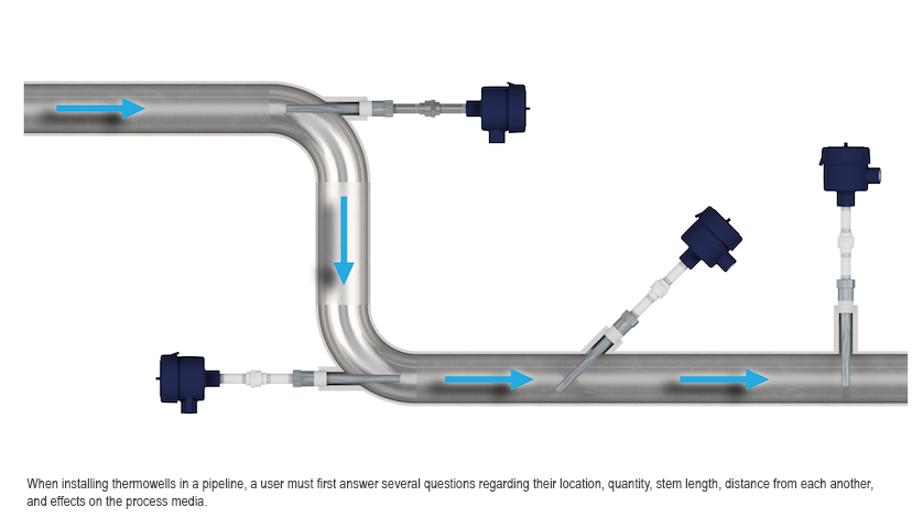
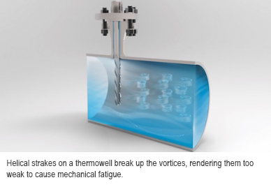
The goal is to balance the potential for mechanical failure and the potential for sensing error. On the one hand, the longer the insertion length, the greater the chances that the thermowell will bend or suffer mechanical fatigue due to the process media’s velocity. On the other hand, the shorter the insertion length, the greater the chances that users will see unreliable results due to poorer heat transfer. In summary, there is not one perfect stem length for a thermowell, but a goal of balancing outcomes.
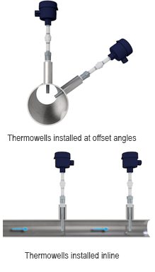
    One way to reduce vibration and mechanical fatigue is to use a thermowell with a ScrutonWell? design, which has helical strakes to suppress vortex-induced vibrations. Rigorous endurance tests have prove the effectiveness of the ScrutonWell? Design as a vortex breaker.

  2. Multiple thermowell installations
    Most of the time, one thermowell with a temperature sensor is sufficient for a section of pipe. However, some processes call for multiple thermowells in an area. The key when installing several thermowells is to minimize their influence on one another while providing a consistent flow character in the process. There are two ways to do this:

    Thermowells installed at offset angles - Thermowells installed inline Offset angles In this scenario, both thermowells are installed at the same location but at angled offsets from each other. By having them at the same location, they are not influenced upstream or downstream from an inline installation. They should be installed at a minimum angular offset to allow for easy installation and removal. Also, the thermowell tips should be far enough away from each other so as to not influence each other’s readings.

    Inline – To ensure laminar flow in the process, the distance between thermowells can vary from 10 to 100 times the pipe diameter, a wide range indeed! Several factors go into how far apart inline thermowells should be placed, but a conservative estimate is 25 times the pipe size. For example, in a pipeline with a 4-inch (100mm) diameter, the distance between thermowell installations is about 8 feet (2.5m): 4″ x 25 = 100″ = 8.33′.
     
  3. Elbow installations
    The installation in an elbow allows the sensing area of the thermowell to be placed in the centerline of the pipe, ensuring an optimal location for measuring the process’s temperature. There are two different sites of thermowell installations in an elbow:

    Thermowell installations in elbows: A. facing upstream, B. facing downstream
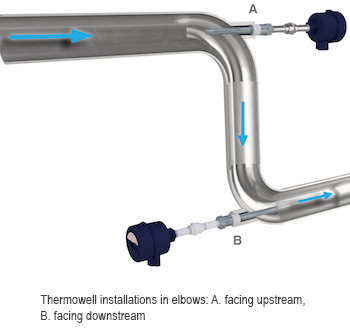
Facing upstream – The thermowell tip (temperature sensing area) is upstream of any influence, such as mixing or swirling, of the elbow. Many users prefer this elbow installation over “facing downstream” (see next bullet), although the bending moment calculations to ASME PTC 19.3 TW-2016 are outside the scope of this standard.

    Facing downstream – The thermowell tip is downstream of the elbow, which means that it can be influenced by any mixing or swirling that the elbow causes. The advantage when performing thermowell wake frequency calculations is that facing downstream takes a conservative approach and assumes it is a perpendicular installation.


Other considerations for thermowell installation

Thermowell length, distance apart, and location are the main considerations when installing these protective fittings, but they are not the only ones. Users should also keep in mind these other factors:

  • Pipe size – ranging from small (2″ to 4″) to large (> 60″)
  • Process media – whether it’s gas or liquid
  • Two-phase flow – such as gas and liquid, two different liquids, a liquid and solid particles, or a gas and solid particles
  • Type of flow – steady or pulsating
  • Distance from other measuring instruments or fittings


Talk to one of our experts today at (855) 737-4714 or fill out our online form to learn more.


How to Select a Pressure Gauge

WIKA

Selecting a pressure gauge is a lot like buying a car. The marketplace is filled with manufacturers, each offering various makes and models with different features. When deciding on a vehicle, buyers look at factors such as the seats and storage space needed (two-seater, sedan, station wagon, minivan), primary driving conditions (city, highway, racing, towing), transmission type (manual, semi-automatic, automatic), and fuel (gasoline, hybrid, electric, hydrogen fuel cell). Cost, of course, is another important consideration.

When choosing a pressure gauge, buyers go through a similar process but with different priorities. Here’s a quick tutorial on how to select a pressure gauge.
 

Digital or Mechanical Pressure Gauge?

How to Select a Pressure Gauge
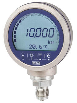
In the world of pressure measurement, the equivalent of a supercar is a digital gauge. With an accuracy of up to ±0.025% of span, this instrument is so precise and high-performance that it can be used for calibration. Top-of-the-line digital gauges like the CPG1500 also communicate wirelessly, a necessity for remote monitoring and industrial IoT (Internet of Things). Understandably, digital gauges are expensive.

Most industrial processes do not require that level of accuracy or number of features. A mechanical, or analog, pressure gauge is sufficient.


Steps for Selecting a Mechanical Gauge

There’s a simple mnemonic for remembering the seven factors for gauge selection: STAMPED.

Size, Temperature, Application, Media, Pressure, Ends, Delivery Time
  1. Size
    Mechanical pressure gauges come in a variety of nominal sizes, and the one you choose depends on your requirements for readability, space, and precision. The larger the dial face, the more gradations it will have for more exact readings, and the easier it can be seen from a distance – an important consideration if technicians cannot get close to the gauge. However, some applications don’t have room for a large pressure gauge. WIKA gauges range from 1.5″ (40 mm) to 10″ (250 mm).

    Another factor to keep in mind is that the size of the end connection will determine what sizes of gauge are available. For example, a 1.5″ gauge is too small to accommodate a ? inch size connection, based on the wrench flat area in proportion to the case profile.

    Regardless of the gauge size, low-light situations make it difficult to read a dial. At WIKA, many of our gauge dial faces come with the option of InSight?, a retro-reflective material, or InSight Glow?, which is InSight? with the addition of photo luminescence for visibility during power outages.
     
  2. Temperature
    Both the ambient temperature and media temperature will determine the material of the wetted parts (brass, stainless steel, nickel alloy, etc.) and whether it will have a dry case or be liquid-filled. The lower the ambient temperature, the more likely it is that a liquid-filled gauge is the right choice. Gauges in extremely cold environments, like the oil fields around the Arctic Circle, are filled with a special low-temperature silicone oil to prevent the internal parts from icing.

    If the media temperature will reach 140°F (60°C) or higher, use a stainless steel gauge. This is because brass gauges are soldered, and solder begins to break down at that temperature. We’ve seen customers who used brass gauges for steam applications based on price, and those gauges failed since steam exceeds the 140°F threshold for solder. SS gauges can withstand temperatures up to 392°F (200°C), depending on the configuration.

  3. Application
    Basically, in what industry will the gauge be used? Here are some examples: Gauges for drinking water applications need to be lead-free, while process industries like refineries and pharmaceuticals require industrial process gauges. Cryogenic gas tanks call for a pressure solution that measures both differential pressure and working pressure, and is cleaned for oxygen service. Gauges used in sanitary processes must have a hygienic design. The highly aggressive gases used in the semiconductor industry means these applications need gauges with an ultra-high purity (UHP) design. What‘s more, some applications require special approvals. For example, gauges for use with fire sprinklers must have UL (Underwriter Laboratories) and FM (Factory Mutual) approvals.

    For reliability and long service life in high-vibration applications, use a liquid-filled gauge to dampen movement and protect the instrument’s internal mechanism. Note that in high-pressure cycles (pulsation), liquid fill should be used in conjunction with a restrictor or a snubber.

    Some common questions we hear have to do with these accessories. What’s the difference between a restrictor and snubber? Besides dimensional restraints, when would a snubber be the better choice? Restrictors are a less expensive option for gauges in applications with dynamic pulsation. However, they are limited based on the orifice size, and they are prone to clogging in debris-filled media such as wastewater. Snubbers mitigate dynamic pulsations and pressure spikes much like restrictors, but they come in a wider range of sizes and are not as prone to clogging. Snubbers are also more adjustable in the field with the use of interchangeable pistons or external adjustment screws, and this flexibility reduces downtime.

  4.  Media
    The media that the pressure gauge, especially its wetted parts, comes in contact with will determine the gauge material. In other words, what’s in the pipeline? A brass (copper alloy) gauge is suitable for water, air, or other non-aggressive liquids or gases. But sour gas (hydrogen sulfide), ammonia, creosote, and other harsh chemicals require corrosion-resistant materials such as stainless steel or a nickel-copper alloy like Monel?. For media that can clog gauge mechanisms, opt for the addition of a diaphragm seal, which provides a physical barrier between the fluid and the pressure instrument.

    The media also affects the type of case filling used. Glycerin is the standard fill fluid for non-oxidizing environments, while highly reactive media call for an inert oil like Halocarbon or Fluorolube?.

  5. Pressure
    This question encompasses several aspects. First, what type of pressure do you need to measure – gauge pressure (working pressure), absolute pressure, or differential pressure?

    Second, what is the operating range of the application? In general, select a gauge whose range is 2X the optimal operating pressure, as this ensures the best performance. Standard pressure gauges can handle up to 20,000 psi (1,600 bar), with specialty products like the PG23HP-P going as high as 87,000 psi (6,000 bar). For low pressure measurements, use a capsule gauge to detect small pressure differences in units such as millibar (mbar), inches of water column (inH2O), or ounces per square inch (oz/in2).

    Finally, what is the desired pressure scale? Gauges come in a variety of measurement units – e.g., psi, bar, kPa, inH2O. All WIKA gauges can be customized, such as dual scale, triple scale, or custom scales, based on your application needs.

  6. “Ends” (process connections)
    What “ends,” or process connections, do you need? The most common type in the U.S. and Canada is NPT, while other countries tend to use G (metric) connections. Then for each type there’s the question of connection size, such as ?, ?, and ?. And finally, the location of the process connection; the two most common connection locations to choose from are lower (bottom) mount or back (rear) mount.
     
  7. Delivery time
    Most buyers don’t consider this last factor, but the issue of delivery time is very relevant. If you need a large quantity by tomorrow, your choices will be standard gauges in popular nominal sizes that are already on the shelf. But if you can wait a few weeks, you’ll be able to get the exact pressure gauge you want with all the desired options.


WIKA’s System for Model Numbering

With a few exceptions, WIKA’s mechanical gauges have a five-digit model number. The system may look complicated, but it’s really quite simple. Let‘s take the model 213.40 Bourdon tube pressure gauge as an example.
Part number 213-40

A. Instrument series or type
1 = standard (100 series): general purpose, low cost
2 = industrial (200 series): high quality
3 = test gauge: high precision
4 = Sealgauge?: diaphragm gauge
5 = absolute pressure gauge
6 = capsule gauge (600 series): low pressure
7 = differential pressure and duplex gauges
8 = Electronic Pressure Measurement line
9 = diaphragm seal

B. Basic instrument type
0 = special type
1 = copper alloy (brass)
2 = steel
3 = stainless steel
4 = nickel-iron alloy (Ni-Span C?)
5 = plastic (coating or lining, not sensing element)
6 = nickel-copper alloy (Monel?)

C. Case filling
0 = special type
1 = standard type
2 = dry case, with increased water protection
3 = liquid-fillable case or liquid-filled case
4 = square or rectangular housing

D. Design features
10 = standard design (lower mount connection in 100 series)
11 = compressed gas gauge or small size stainless steel
12 = standard design (center-back mount connection in 100 series)
13 = liquid-filled ABS plastic case
15 = special stainless steel gauge
20 = heavy-duty case
25 = hinged ring design
30 = solid-front, blow-out back case (safety case)
34 = fiberglass reinforced thermoplastic case (XSEL? process gauge)
40 = forged brass case
41 = special design for mining industry
50 = All stainless steel construction
52 = gas density monitor or controller
53 = stainless steel case, O-ring or welded connection to socket, crimped ring bezel
54 = stainless steel case, O-ring or welded connection to socket, bayonet ring

Using this chart, we can see that the 213.40 is an industrial gauge (200 series) made of brass, is liquid-fillable/liquid-filled, and has a forged brass case. This is WIKA’s hydraulic gauge, as it is designed to withstand extreme shock, vibration, and pulsation.

Talk to one of our experts today at (855) 737-4714 or fill out our online form to learn more.