Precision Linear Motion in California for High-Performance Automation
Valin Corporation
California’s Innovations Driving High-Performance Automation
 California is home to some of the world’s most demanding precision industries — from semiconductor manufacturing in Silicon Valley and chip fabs in Central California, to advanced medical device production in San Diego and aerospace systems across the state. Whether you’re building high-throughput inspection systems, lab automation platforms, or next-gen optical assembly equipment, motion precision isn’t a nice-to-have — it’s mission-critical.
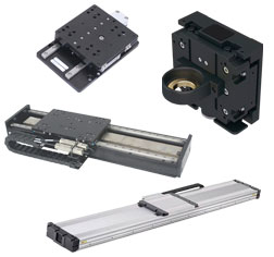
At Valin, we help California automation teams engineer solutions that deliver repeatable accuracy, high bandwidth, and optimal throughput by selecting the right linear motion technology for the job: linear motors where speed and responsiveness matter, and ball screw and lead screw stages where cost-effective precision and load handling are key.
Exploring Linear Motor Technology for High-Speed Precision
Linear servo motors offer a frictionless direct-drive architecture that eliminates mechanical backlash and maximizes responsiveness. For California manufacturers pushing the limits of throughput and precision, these motors shine:
- High traverse speeds with sub-micron smoothness
- Zero backlash and high stiffness for dynamic motion control
- Ideal for semiconductor wafer handling, inspection scanners, and pick-and-place systems
- Fast settling times for high throughput production lines
Learn more about Linear Servo Motor Positioners. When paired with high-precision linear rails or bearings, high-resolution linear encoders and quality integration, linear motor stages are key in meeting the needs of high-precision applications.
In applications like lithography inspection or high-precision lab automation, the ability to accelerate and decelerate rapidly without losing positional accuracy is what separates “good enough” from “leading edge.”
The Role of Ball Screw Stages for Versatile Precision
When the application calls for high precision with robust load support and cost-efficient design, linear ball screw and lead screw systems are often the right answer. These actuators convert rotary motion into linear motion with superb repeatability and excellent positioning accuracy — especially suited for:
- Assembly and test automation
- Metrology systems
- Optical equipment alignment
- High-precision motion under load conditions
Discover the range Linear Ballscrew & Leadscrew Actuators.
Ball screw stages excel where repeatability and load handling are priorities, and where high speed is less critical than positional stability and cost value.
Advantages of Precision Automation Solutions
High-precision automation solutions allow for faster throughput with shorter cycle times, less waste, and finer control than less precise solutions. This helps industries requiring precision linear motion in California to advance.
For example, high-speed and precision was required to increase DNA synthesis and analysis many times over, which dropped the price significantly leading to the mapping of the entire human genome and better drug discoveries.
In the semiconductor industry, high-precision control continues to be critical as chips get smaller and more difficult to manufacture.
These advantages are met by truly understanding the applications and finer details of motion controls systems as discussed in the article The Many Layers of Performance and Specifications in Motion Control
How to Choose: Linear Motor vs Ball Screw Stage
Rather than pick “the best” in a vacuum, it’s better to match technology to the specific dynamics of your application. Here’s a practical way to think about it:
- Speed & Responsiveness: If your process requires fast acceleration, deceleration, and fine positional control with minimal mechanical losses, linear motors often win.
- Load & Cost Constraints: For heavier loads, longer stroke lengths, or cost-sensitive systems where extreme speed isn’t needed, ball screw and lead screw stages are highly effective.
- Environment & Lifecycle: In cleanroom or high-duty-cycle environments, consider lubricant compatibility, service access, and long-term positional stability.
Learn more about Ball Screw vs Belt & Pulley vs Linear Motor actuators.
We help California automation engineers compare these technologies against real demands — from gantry systems on factory floors to precision integrators in lab settings.
Valin’s California Presence — Support When & Where You Need It
Valin’s regional teams understand California’s industry nuances — from cleanroom requirements in semiconductor lines to traceability and quality standards in medical device manufacturing.
We provide:
- Product selection and sizing recommendations
- Motion system integration support
- Application engineering and performance tuning
- Local service and parts availability
Whether you’re in Silicon Valley (Cupertino, Fremont, Santa Clara, San Jose), Sacramento, San Diego, or the Central Valley, our engineers are ready to support complex motion challenges.
Start Your Precision Motion Project
Precision doesn’t happen by accident. It starts with understanding how motion technologies differ — and choosing the solution that aligns with your performance, reliability, and cost goals.
Explore our products, or connect with Valin’s motion specialists to architect the right system for your California application.
Explore Products:
Engineering a Reliable Fuel Delivery Solution for a Carbonized Biomass Manufacturer
Sri Gavini || Valin Corporation
Thermal processing systems used in carbonized biomass production rely heavily on stable and predictable fuel delivery. In kiln operations where temperature profiles directly influence material characteristics, even modest fluctuations in gas pressure or valve response can lead to uneven heating and inconsistent results. For this reason, propane distribution hardware is often treated not as an auxiliary system, but as a critical process component.
A U.S. manufacturer operating kilns for agricultural and environmental applications required a propane manifold assembly capable of supplying multiple distribution points from a common source. The system was intended for continuous operation in an industrial setting and needed to support consistent flow control, reliable shutoff and long-term maintainability.

The manufacturer provided an initial layout and component list that outlined the intended configuration. While the overall concept was sound, further review revealed several practical issues that warranted closer attention. Some components were difficult to source within the project schedule, while others introduced unnecessary complexity or cost. In addition, aspects of the mechanical layout raised questions related to accessibility, measurement reliability and long-term service.
As the design progressed, attention shifted from individual components to system behavior. Flow paths were reviewed with an emphasis on minimizing pressure losses and avoiding unnecessary restrictions. Tubing runs were adjusted to reduce mechanical stress and accommodate thermal expansion without relying on excessive supports or tight bends. Particular care was taken with pressure sensing locations, as their placement and orientation can significantly influence measurement stability in gas service.
Instrumentation and control elements were evaluated based on response characteristics, durability and compatibility with propane service. Valve actuation behavior, sealing performance and electrical interface requirements were considered alongside environmental exposure and expected duty cycles. Pressure regulation was treated as a dynamic requirement rather than a static setpoint, accounting for startup conditions and transient changes during kiln operation.
Once the mechanical and control details were resolved, fabrication proceeded as a unified assembly rather than a collection of subassemblies. This approach allowed tubing alignment, component spacing and mounting details to be verified in context rather than in isolation. During assembly and testing, several common issues associated with custom gas systems were encountered, including minor leakage at threaded connections and small fitment conflicts between instruments and mounting geometry. These were addressed through iterative adjustment and verification rather than wholesale redesign.
Each completed assembly was pressure tested under operating conditions for an extended period to confirm leak integrity and overall system stability. Visual inspection and functional checks were used to verify correct orientation, labeling, and control response prior to shipment.
In operation, the completed manifold provided stable and repeatable fuel delivery consistent with the requirements of continuous kiln processing. Beyond the immediate application, the design process highlighted the value of early system level review and close attention to mechanical detail in gas distribution systems. Small decisions related to layout, orientation and sourcing had measurable impacts on reliability, serviceability and commissioning effort.
While the project began as a single manifold request, the outcome informed subsequent discussions around standardization of similar systems and future integration with control panels and instrumentation. The work underscores how incremental engineering refinement, rather than major redesign, often plays the largest role in translating a conceptual layout into a dependable industrial system.
Key Highlights
- A comprehensive approach was taken to design a propane manifold system supporting multiple distribution points from a single source for kiln applications.
- Mechanical layout adjustments focused on reducing stress, accommodating thermal expansion, and improving accessibility to enhance long-term maintainability.
- Pressure sensing and control components were carefully evaluated to ensure measurement stability and response reliability in propane service.
- Iterative testing identified and resolved common issues such as leaks and fitment conflicts, ensuring system integrity before shipment.
- The project demonstrated the critical role of early system-level review and incremental refinement in developing dependable industrial gas distribution systems.
Case study published in Processing Magazine
Pressure Gauge Know-How: Difference Between NPT and G Connections
WIKA

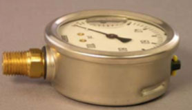
Have you ever looked at a pressure gauge in a pipe assembly and wondered which connection type it has? Perhaps you have to replace a measuring instrument or need to buy a new one. One way to find out is to remove it from the installation and look at its threads, but this will result in downtime if the process is active. There is an easier way to tell whether a gauge has an NPT or G connection.
NPT Connections in Pressure Gauges
 Most of the time, the answer depends on geography. In the U.S. or Canada, the pressure gauge will most likely come with an NPT (National Pipe Tapered) connection. This thread type, standardized by ANSI (American National Standards Institute) and ASME (American Society of Mechanical Engineers), is typical among North American measuring instruments, found in piping systems, pumps, compressors, plumbing systems, mobile working machines, and many more applications.
Male (external) NPT connections are somewhat conical, with the diameter of the threads decreasing slightly from socket to tip. Tapered threads seal along the flanks of the thread. Due to the spiral leak path, however, Teflon? tape (PTFE) or a sealing compound is required to create a good seal. The most common sizes for pressure gauge connections in the U.S. are ?-inch NPT, ?-inch NPT, and ?-inch NPT.
The U.S. and Canada also use parallel threads like the NPSM (National Pipe Straight Mechanical) connector. However, this thread type is typically found as a female (internal) component in non-pressurized devices like thermowells.
The tapered shape of the NPT threads allows users to continue turning the connection several more degrees after making the seal, until the instrument reaches the desired position. Tightening, though, has to be done with care: Too much compression can lead to galling, and over-tightening can damage the threads. These situations are problematic in applications that require regular installation and removal of the pressure gauge.
G Connections in Pressure Gauges
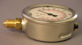 If the pipe assembly is in Europe, Asia, or Latin America – basically anywhere else in the world but the U.S. and Canada – the pressure gauge will very likely have the straight threads of a British Standard Pipe Parallel (BSPP) connector, denoted by the letter G*. The tapered variants from the BSP classification system are denoted by ISO7, for example, R1/4-ISO7.
They are often referred to as metric connections because they are used in the metric system, and the dimensions are based on metric measurements. G connections have a straight body (constant diameter) with parallel (straight) threads. The main purpose of the parallel threads is to contain the pressure, which allows for regular installations and removals without damaging the thread. A sealing washer is required to seal the connection. As sealing of the connection takes place on the washer and not on the thread itself, no sealing compound or PTFE tape is required.
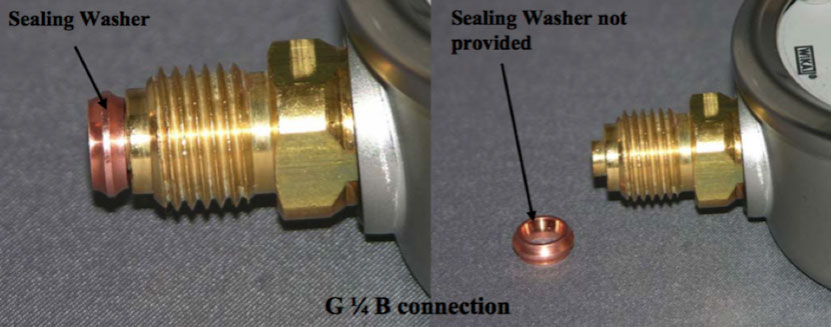
Since the thread of a G connection will bottom out at the wrench flat, no threads are left exposed. Once the connector bottoms out to make the seal, the positioning of the instrument cannot be changed. To avoid the problem of awkward gauge positioning, use a “crush washer” and hand-tighten the connection. At the resistance point, approximately 1? turns are left before the crush washer flattens out. This leeway allows the user to fine-tune the pressure gauge’s final position with a wrench**. If the position of the instrument is not critical, a flat washer can be used instead.
Eyeballing the Difference Between NPT and G Connections
When placed side by side, the difference between the two connection types is clear. The NPT thread is slightly tapered, while the G connection is straight. Another obvious visual: The G connector ends with a small protrusion (nipple), used to center the gasket. If calipers are handy, a third method is to measure the angle between threads: NPT threads are 60°, while BSP threads are 55°.
But how about when the pressure gauge is already inserted into the process? Is there an easy way to tell which connector type an instrument has without removing it? Yes. Because a G connection bottoms out, no threads are visible. In an NPT connection, a few threads or exposed PTFE tape can be seen.
NPT vs. G Connections
| NPT Connections | G Connections | |
| Thread Shape | Slightly apered | Straight |
| Tip of thread | Blunt | Small protrusion (nipple) |
| Thread angle | 60° | 55° |
| Visual when assembled | Visible thread or PTFE tape | No exposed thread |
Talk to one of our experts today at (855) 737-4714, or fill out our online form to learn more.
Six Common Causes for Thermocouple Temperature Measurement Errors
WIKA
Thermocouples are robust temperature measurement devices that are accurate enough for many industrial and scientific applications. Relatively inexpensive compared to other temperature measurement technologies, thermocouples are valued for their ability to measure a wide temperature range: from –200° to +1250°C (–328° to +2282°F).
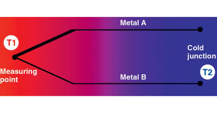
Thermocouples measure temperature differentials, not absolute temperatures. Two wires, each made from a different metal, are joined at the tip. This is the measuring junction. At the other end, the wires are connected to a body of a known temperature, called the reference junction. A thermocouple works by taking the difference in voltage between the two junctions, explained by the Seebeck effect. The measured voltage is converted into a temperature unit, with the temperature reading displayed on a device or transmitted to a remote location.
Although thermocouples are reliable, temperature measurement errors can occur for various reasons. The following are the six most common causes of thermocouple measuring errors, followed by ways to rectify them:
1. Selecting the Wrong Type of Thermocouple on the Transmitter
You can run into problems if you choose the wrong type of thermocouple when inputting the settings into the transmitter during installation. This is a common error, as there are numerous types of thermocouples – types K, J, N, E, T, R, S, and B – each with a different range, accuracy, and electrical output.
Solution: Almost all thermocouples are color-coded by type, so you usually just need to confirm the color of the thermocouple jacket and match the settings on the transmitter.
For a quick reference on thermocouple color codes, including international standards, download our chart.
2. Problems Related to the Thermocouple Extension Wire
If you accidentally reverse the polarity of the thermocouple lead wires, the measured temperature will be incorrect by the difference in temperature between the two ends of the leads. The problem is understandable because red is the usual color for positive charges, whereas the red wire in thermocouple cables typically contains the negative signal. This coloration is the ANSI standard for thermocouples, but it is not what most people expect.
Solution: Double-check the connection and, if necessary, swap the thermocouple lead wires.
3. Inherent Variations in Alloys
No two batches of wires are exactly alike. As the alloy percentages vary a tiny bit during each manufacturing process, some error in thermocouple accuracy is unavoidable. Standard thermocouples get within approximately 1% of the actual temperature at the measuring junction, which is accurate enough for most applications.
Solution: Order thermocouples with special-limit wires, which can improve accuracy twofold. These wires are manufactured at the highest tolerances to ensure the fewest possible impurities and the greatest consistency in alloy ratio.
4. Temperature Variations Around the Reference Junction Connection
Because a thermocouple measures temperature differentials, any temperature fluctuations around the reference junction (cold junction), which has the known temperature, result in an erroneous temperature reading.
Solution: Make sure no fans or other sources of cooling or heating are located near the reference junction. Simple insulation can also protect the junctions from extreme temperatures.
5. Thermocouple Grounded at More Than One Location
A thermocouple should be grounded at only one location. If it is grounded at more than one location, a “ground loop” can be created with current flowing through the thermocouple from one ground to the other. This is likely to generate electromagnetic fields, which can lead to radio-frequency-interference-related problems that can impact measurement accuracy.
Solution: Ground either the transmitter (connection head) or the controller/recorder, but not both. Selecting transmitters that have internal isolation between the input, output, and ground usually provides enough isolation to eliminate a ground loop. Loop isolators are also available and can be put in the loop wiring circuit to prevent this from happening.
6. Thermocouple Age
While thermocouples are reliable temperature measurement devices, they do drift with time. Maximum exposure temperature, cyclic measurements, and frequency of the cycles affect the metallurgy with a resultant drift, usually downward. Unfortunately, this drift cannot be predicted, but 10-20°F errors are common.
Solution: The only solution is to periodically replace the thermocouple based on the user’s experience.
Talk to one of our experts today at (855) 737-4714, or fill out our online form to learn more.
Pressure Measurement: Understanding PSI, PSIA and PSIG
WIKA
 Pressure measurement is all about PSI. That’s because pounds per square inch (PSI) is the most common unit for measuring pressure in the U.S. It’s important to understand what PSI means and how it is used, as pressure measurement is an important part of life in the 21st century. For example, you need to make sure that your car tires or bicycle tires are inflated to the proper PSI before you drive or ride, and today, equipment of all types includes pressure sensors or gauges to assist in monitoring and diagnostic operations. Moreover, scores of careers, ranging from civil and mechanical engineers to meteorologists to refinery pressure instrument technicians, also involve understanding and using pressure measurements as a part of their daily activities.
Getting a Grip on Pounds per Square Inch — PSI
Pounds per square inch is the unit of pressure used the vast majority of the time in the United States for household, commercial, or industrial equipment. Other countries measure pressure in different units. In scientific contexts (physics labs and so forth), pressure is typically measured in much smaller units called pascals (named after French physicist Blaise Pascal). For reference, 1 PSI equals 6,894.76 pascals. Pressure measurement instruments such as pressure gauges and sensors typically display measurements in PSI. Two frequently used variations of PSI are PSIA and PSIG.
Pounds per Square Inch Gauge – PSIG Vs. Pounds per Square Inch Absolute – PSIA
PSIG
PSIG is the term for pressure specified by a gauge or other pressure measurement device. It gives the difference between the pressure in a pipe or tank and the pressure of the atmosphere (atm).
PSIA
PSIA is a term that describes the absolute pressure in PSI, including the pressure of the atmosphere. Absolute pressure is also sometimes referred to as “total pressure.”
Examples of How to Calculate PSIG and PSIA
Note that PSIG is always lower than PSIA. The formulas to describe the relationship are: PSIG + 1 atm = PSIA and PSIA – 1 atm = PSIG (where atm is atmospheric pressure). It is easy to calculate PSIA or PSIG or convert between the two. You can use the actual atmospheric pressure value for your location if it is available, or you can also use 14.7 psi (the approximate atmospheric pressure at sea level) as a standard value to convert PSIG to PSIA and vice versa. (Unless you live at a high altitude or in a deep valley, the sea level value will work.) In other words, since atmospheric pressure at sea level is 14.7 PSIA, you subtract the PSIA of 14.7 from an atm pressure of 14.7 to equal zero PSIG (14.7 (PSIA) – 14.7 (atm) = 0). As an example, absolute pressure at sea level is 14.70 PSIA, and absolute pressure at an elevation of 1,000 feet is 14.18 PSIA. At the higher elevation, there is less pressure, so if an absolute pressure gauge is read at a 1000-foot elevation, its readings will be close to 0.5 PSI (14.70 – 14.18 = 0.52) less than those from a standard pressure gauge.
Talk to one of our experts today at (855) 737-4714, or fill out our online form to learn more.
Pressure Sensors, Pressure Transducers, and Pressure Transmitters: What’s the Difference?
WIKA

What‘s in a name? When it comes to electronic pressure sensing, the answer for many users is “not much.” Manufacturers do not always or consistently differentiate between a pressure transducer and a pressure transmitter, while some devices are simply called a pressure sensor. It’s easy to see why, as all three terms refer to functionally similar instruments that measure and convert the physical property of pressure into an electronic signal.
Other names for electronic pressure measuring instruments include I/P (current to pressure) converters and I/P transducers, P/I or P to I (pressure to current) converters, pressure senders, and pressure switches.
Some of these are legacy terms, part of the industry’s or manufacturer’s history, while for certain users, it’s a matter of personal preference. It’s little wonder that the market tends to lump together all devices with a wire and refer to them all as simply pressure sensors!
The Types of Electronic Pressure Measurement Instruments
The textbook definition of a transducer is an instrument that measures pressure, load, force, or other states, and converts the reading into an electronic signal. A transmitter also converts a reading into an electronic signal, but it then amplifies, modifies, and sends that signal to a receiver. A switch is a device that, based on a preset switch point, interrupts the current or diverts the current from one circuit to another.
At WIKA, a transducer (like the TTF-1) has a non-amplified output, while a transmitter (like the A-10 or S-20) has an amplified output. Other electronic pressure devices are simply called a sensor, as this is an easy way to refer to next-generation instruments like the A-1200 with IO-Link or the MH-4-CAN with CANopen and SAE J1939 CAN communication protocols. All the above electronic pressure measuring instruments are listed under the category pressure sensors, while pressure switches are grouped separately.
Comparing Pressure Transducers and Transmitters
In a pressure transducer, a thin-film or piezo-resistive pressure sensor is mounted on a process connection. The transducer converts pressure into an analog electronic output signal, typically as a millivolt per volt output. These signals are not linearized or temperature compensated.
A pressure transmitter has additional circuitry that linearizes, compensates, and amplifies the signal from a transducer. The different signal types are typically voltage signals (e.g., 0 to 5 or 0 to 10 volts), milliamps (e.g., 4 to 20 milliamps), or digital. The instrument can then transmit the signal to a remote receiver.
Many pressure transmitters offer a variety of calibration options, including turndown and zero/span adjustment. Smart transmitters can be calibrated, tested, and reset remotely using a bus network.
Pressure Transducer or Transmitter: Which One to Choose?
Despite the amplified vs. non-amplified differences between transmitters and transducers, it really doesn’t matter what people call them or which ones they use. What’s more important is whether the device suits a particular application and offers the needed output. Accuracy, range, working temperature, and the medium are all determining factors when selecting the right pressure instrument for an application.
As for the output signal, here are some factors to take into account:
- Typical mV outputs do not have temperature characterization.
- A current signal is more immune to interference and noise than a voltage signal.
- A current signal can also travel farther.
- An analog signal is just the pressure reading.
- A digital signal allows a user to collect more information and other variables besides pressure.
- The input card of many control systems accepts only amplified signals.
The bottom line: Get the pressure device you need, regardless of what it’s called.
Talk to one of our experts today at (855) 737-4714, or fill out our online form to learn more.
The Magnetic Level Indicator Working Principle: Simple and Effective
WIKA
The magnetic level indicator working principle is based on the effects that one magnet has on nearby magnets. The mechanics are simple yet very effective, yielding reliable and repeatable level information for continuous monitoring and recording of fluid levels.
What Is the Magnetic Level Indicator Working Principle?
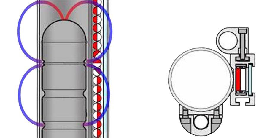
 The working principle behind a magnetic level indicator is that the measuring instrument shares the same fluid — and therefore, the same level — as the vessel. The level indicator is attached to the vessel and connects directly with the fluid to be measured. Within the chamber is a float with a magnet assembly inside. This float rests on the fluid’s surface. As the fluid level rises or falls, so does the float. As the float moves up or down, the magnet assembly rotates a series of bi-color magnetic flags or flaps, changing the visual indicators mounted just outside the chamber from one color to the other.
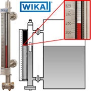
Since the magnetic level indicator working principle relies on the interaction between magnets, these level measuring instruments do not need a power source. They are also virtually maintenance-free. An additional advantage: The indicator’s magnetic force can affect optional switches or transmitters mounted outside of the chamber. The colored flags are easy to see, even from a distance, and are paired with a scale for precise readings. As for any level instrumentation, the size and material of the float are chosen according to the media, temperature, pressure, and density of the process media.
WIKA’s High-Performance Magnetic Level Indicators
WIKA has over 60 years of experience in this field, as our subsidiary KSR-Kuebler obtained one of the first patents for a magnetic level indicator. WIKA manufactures the WMI series, a complete line of high-quality magnetic level indicators that provide years of accurate level information. The float in each MLI is designed for each application. The materials of the float magnet are carefully chosen to minimize the size of the float and the chamber, and to provide the best coupling for the particular pipe wall material and thickness. Bypass chambers can be made of several different types of stainless steel and alloys (Hastelloy?, Inconel?, etc.) and other materials (Teflon?, PVC, etc.) to suit media and process temperature.
Model WMI magnetic level indicators are highly adaptable. They work from ?320°F to 1,000°F (?195°C to 537°C), from full vacuum to 5,000 psi (344 bar), and for specific gravities as low as 0.35. Indicator flags can be red–white, yellow–black, or fluorescent. The scales can be indicated as imperial units (feet/inches), metric units (mm/cm/m), percentages, or even customized to your specific requirements. You can also choose from several process connections, connection sizes, vents, and drains. Other useful options include high-temperature insulation and cryogenic insulation.
WMI magnetic level indicators fit most industrial and commercial applications in:
- Refinery and chemical industries
- Energy and power plant technology
- Feed water heaters and boilers
- Oil and gas industries
- Offshore exploration and drilling
- Pipeline compressor applications
- Pulp and paper
- Food and beverage
- Gas plants
- Pharmaceutical
A level instrument based on the magnetic level indicator working principle can give you the accuracy and reliability you need. WIKA can help you find the best one for your application.
Talk to one of our experts today at (855) 737-4714, or fill out our online form to learn more.