If you are an engineer, operator or technician who is responsible for system performance and safety, you know that pressure instruments play a critical role in your process and industrial/OEM applications.
These instruments provide accurate, reliable pressure measurements to confirm whether systems are operating effectively and efficiently, or if adjustments are needed. This information helps protect personnel, improve process efficiency and maintain product quality.
What Happens When Instruments Fail?
There are many causes of instrument failure, and these issues can create serious problems for your operation. The good news is, in most cases, they can be prevented.
Read this guide to learn how to recognize the early warning signs, the most common pressure instrument failures and how to address them before they happen.
While the focus of this guide is on pressure gauges, the information provided also applies to pressure switches and transducers.
What to Look for Before Failure Happens
Regular instrument maintenance is essential for ensuring safety, process efficiency and product quality. It also makes it easier to identify issues early and apply the right solutions before they escalate. This proactive approach helps reduce costly service work, minimize unplanned downtime and lower the risk of equipment-related injuries.
Top Three Signs of Failure
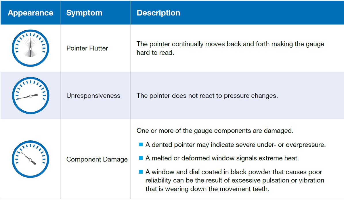
These signs, among others, serve as indicators of underlying gauge issues. If you can recognize them and understand their causes, you will be better prepared to diagnose and resolve problems that may occur in your own instruments.
6 Common Problems & Solutions
Below are six of the most common pressure instrument problems, why they occur, how they affect your system and steps you can take to resolve them.
1. Problem: Excessive Pulsation or Vibration
In processing equipment, surges in pressure can cause pulsation of the gauge pointer and vibration leading to pointer flutter and gauge component damage.
These conditions generally fall into one of two categories:
- High frequency and low amplitude: The high frequency vibration tends to cause localized wear on the gear teeth within the gauge movement.
- Low frequency and high amplitude: The low frequency vibration creates broader stress on the Bourdon tube and other internal parts.
As a rule of thumb, if pulsations or vibrations cause pointer movement of five percent or more of the full-scale range, steps should be taken to reduce their effect on the instrument.
Solutions:
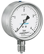
- Dampen the movement or tube: Use a liquid-filled gauge or a dry gauge with PLUS!? Performance to reduce pulsation and vibration effects.
- Install remotely: Mount the gauge away from the pulsation/vibration source using a capillary between 1 and 100 feet in length.
- Restrict process flow: Add a pulsation dampener, throttle screw, steel needle valve or diaphragm seal to reduce pulsation before it reaches the instrument.
 Real world example
A pump station experiencing pointer flutter and frequent gauge damage caused by vibration can switch to a PLUS!? Performance gauge and relocate the instruments away from the vibration source to prevent recurring failures and extend service life.
2. Problem: Operating Outside Temperature Limits
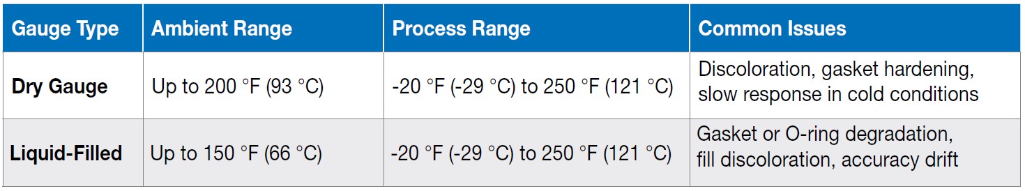
Instruments are designed for specific temperature ranges. Exposure outside those limits can cause significant damage. Refer to Figure A for typical temperature ranges for dry and liquid-filled gauges.
Typical Ranges
- Dry gauges: Up to 200 °F (93 °C) ambient temperature and -20 °F (-29 °C) to 250 °F (121 °C) process temperature. Beyond this, issues such as dial or window discoloration (if acrylic) and gasket hardening may occur.
- Liquid-filled gauges: Up to 150 °F (66 °C) ambient temperature and a similar process temperature range to dry gauges, depending on design. Higher temperatures can cause gasket and O-ring material to degrade and the fill liquid to discolor.
Extremely low or high temperatures can also impact accuracy. For instance, a standard dry gauge may respond more slowly in cold conditions. In general, accuracy shifts when ambient temperatures differ from the calibration point. For gauges calibrated at 68 °F (20 °C), expect a change of about 0.4% for every 25 °F (13.9 °C) above or below that point.
Solutions:
 Real world example
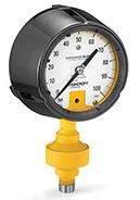
- Remote mounting with capillary: Install the instrument away from the process using a capillary rated from -300 °F to 750 °F (-184 °C to 399 °C) to reduce temperature exposure. Even a short 5-foot length is effective at reducing high temperatures or raising very low ones.
- Direct mounting with dissipating devices: Use an Ashcroft? MicroTube? siphon or finned siphon. This accessory handles pressures up to 5,000 psi and process temperatures up to 800 °F (427 °C). The finned siphon is rated for 3,000 psi and 700 °F (371 °C).
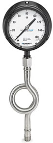
- Coil or pigtail siphons for steam: A pigtail siphon is used for vertical mounting, while a coil siphon is for horizontal mounting. Before installation, fill the loop with water to create a barrier that protects the instrument from high temperature and water hammer.
In a steam application, gauges near the process line could fail due to high temperatures. Adding a siphon between the process and instrument can dissipate heat effectively, preventing fill discoloration and gasket degradation.
3. Problem: Sudden Pressure Spikes
Pressure spikes can result from water hammer, rapid valve actuation, equipment malfunction or process fluid freezing. These sudden surges can dent pointers, rupture Bourdon tubes or break movement gears.
Solutions:
- Integrate an internal stop or overload stop to increase proof pressure by about 20%.
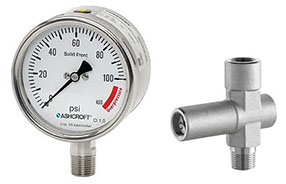
- Install a pressure limiting valve (PLV) such as the Ashcroft? PL02, to automatically shut off flow at the full-scale range and reset once pressure drops.
- Select a gauge with higher overpressure capability. For example, the Ashcroft? T6500 with the XRA option allows overpressure up to 400% of range.
- Choose a new, properly rated gauge that accommodates the maximum operating pressure. For optimal readability, the gauge pointer should normally operate at 12:00 on the dial face. If the normal operating pressure of the gauge is 50 psi, choose a full-scale range that is twice the operating range or 0/100 psi.
 Real world example
In a water treatment facility, you can prevent repeated gauge damage caused by pressure surges during pump start-ups by installing pressure limiting valves to keep spikes from exceeding the gauge’s proof pressure.
4. Problem: Clogging from Particulates and Slurries
Instruments used in dirty processes are prone to buildup that can obstruct flow and reduce accuracy. Processes involving particulates, slurries and sludge, for example, are highly susceptible to clogging. When process material becomes stuck on the instrument’s inner surfaces, it can reduce the efficiency of the process.
Solutions:
- Isolate the instrument from process media using a diaphragm seal or isolation ring.
- Add a flushing connection or valve to clear buildup when needed.
- Use a full-flow isolation ring for heavy sludge or slurries to eliminate clogging.
 Real world example
In chemical processes containing heavy slurries, frequent gauge blockages can occur. Installing diaphragm seals with flushing ports allow operators to clear buildup and maintain accurate pressure readings.
5. Problem: Corrosion from Incompatible Materials
If the wetted parts are not compatible with the process media, corrosion can occur, leading to accuracy loss and possible safety hazards. In severe process conditions, the instrument can fail causing media to escape into the environment and risk operator injury.
Solutions:
 Real world example
- Verify wetted part material compatibility for composition, concentration and temperature.
- Use a diaphragm seal or isolation ring constructed from corrosion-resistant materials if wetted parts are not compatible.
- Refer to the Ashcroft Material Selector & Corrosion Guide for assistance.
In food and beverage cleaning systems, strong sanitizing agents can corrode gauges built with incompatible alloys. Choosing compatible materials helps prevent corrosion-related failures and ensures consistent pressure measurement.
6. Problem: Improper Installation and Use
Instruments are delicate pieces of equipment. Incorrect installation or handling can cause serious instrument damage leading to measurement error or component failure.
Solutions:
- Use an open-ended wrench for installing NPT connections. Do not tighten using the gauge case.
- Do not use the instrument as a step or support after it is installed.
- Inspect regularly for leaks, wear or calibration drift.
Real world example
At a manufacturing plant, gauges often fail after being overtightened during installation. Training maintenance teams to use open-ended wrenches and avoid torquing the gauge case can eliminate recurring damage.
Ashcroft Solutions in Action
Ashcroft Critical Application Solution Experts? (CASE?) help existing and prospective customers identify process challenges and recommend appropriate products and product configurations to resolve or prevent them. The following CASE studies show how our recommended solutions can improve the safety and protection of pressure instrumentation used in critical process applications.
CASE Study: Protecting a Refinery’s HF Alky Unit
 The customer: A refinery with a hydrofluoric acid (HF) alkylation unit, also referred to as an “HF Alky” unit. These units are used in petroleum refining operations to convert isobutane and alkenes (primarily propylene or butylene) into alkylate, which is used to make gasoline.
The problem: Hydrofluoric acid is hazardous and corrosive. If accidentally released, the acid can form a vapor cloud that causes severe reactions and possible fatalities.
The diagnosis: After visiting the plant, reviewing the application and performing on-site analysis of the gauge in use, Ashcroft recommended a gauge assembly with additional safety features for improved protection.
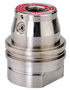
Solution: The gauge assembly we recommended featured the ALD (Acid Leak Detection) system. Its key benefits include:
- Tamper-proof design with the gauge welded to the seal
- Visual indication of leaking process media
- Dual containment for safety
CASE Study: Reducing Extreme Effects in Petrochemical Gauges
 The customer: A refinery using pressure gauges across multiple applications.
The problem: The gauge pointer indicated 42 psi with no applied pressure.
The diagnosis: During a two-day audit, Ashcroft documented each gauge and process at the refinery plant experiencing extreme service conditions, including high temperatures, vibration, pulsation and physical damage. Of all the gauges inspected, 17% showed signs of damage such as discolored fill, overpressure, liquid fill leaks, water ingress, broken windows or loss of pressure containment.
Solution: After determining the root causes of the problems, Ashcroft:
- Replaced most gauges with PLUS!? Performance technology, reducing inventory by 50% and eliminating fill leaks and discoloration.
- Added pressure limiting valves for overpressure protection.
- Specified glycerin-filled gauges for severe vibration areas and IP65 weatherproof cases to prevent moisture ingress.
Prevent Failure Before it Happens
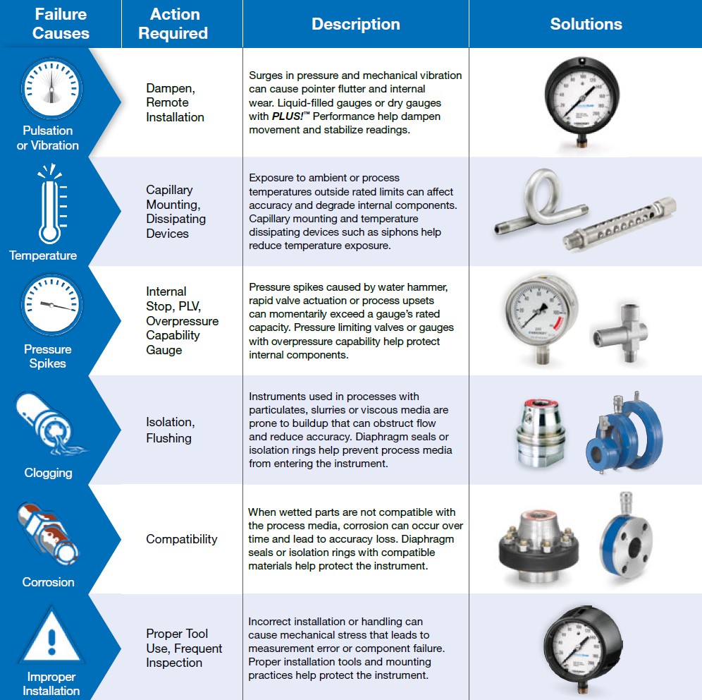
The chart below summarizes the most common causes of pressure instrument failure, the action needed to prevent them and the solutions available to protect your operation.
Access Resources and Get Support
You now have the insight to recognize and prevent the most common causes of instrument failure, so you can help keep your people, processes and equipment safe.
At Ashcroft, we’re committed to supporting you every step of the way, from selecting the right instruments for new applications to resolving issues in existing systems. Our team is here to help you maintain reliable, accurate performance across every operation.
Download How to Avoid Pressure Equipment Failure White Paper
Want to speak to a technical specialist? Contact us at (855) 737-4714 or fill out our online form.